Dimplex DF2024 Service Manual Download Page 2

2             www.dimplex.com

Always use a qualified technician or service agency to repair this fireplace.

!

 NOTE: 

 Procedures and techniques that are considered important enough to emphasize.

 CAUTION:

  Procedures and techniques which, if not carefully followed, will result in damage to the 

equipment.


WARNING:

  Procedures and techniques which, if not carefully followed, will expose the user to the 

risk of fire, serious injury, or death.

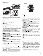
OPERATION  . . . . . . . . . . . . . . . . . . . . . . . . . . . . . . . . . . . . . . . . . . . . . . . . . . . . . . . . . . . 3
MAINTENANCE  . . . . . . . . . . . . . . . . . . . . . . . . . . . . . . . . . . . . . . . . . . . . . . . . . . . . . . . . 4
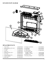
EXPLODED PARTS DIAGRAM  . . . . . . . . . . . . . . . . . . . . . . . . . . . . . . . . . . . . . . . . . . . . 5
REPLACEMENT PARTS   . . . . . . . . . . . . . . . . . . . . . . . . . . . . . . . . . . . . . . . . . . . . . . . . . 5
WIRING DIAGRAM   . . . . . . . . . . . . . . . . . . . . . . . . . . . . . . . . . . . . . . . . . . . . . . . . . . . . . 6
SWITCHBOARD REPLACEMENT   . . . . . . . . . . . . . . . . . . . . . . . . . . . . . . . . . . . . . . . . . 7
RELAY BOARD REPLACEMENT   . . . . . . . . . . . . . . . . . . . . . . . . . . . . . . . . . . . . . . . . . . 7
AC/DC ADAPTER REPLACEMENT   . . . . . . . . . . . . . . . . . . . . . . . . . . . . . . . . . . . . . . . . 8
DISPLAY/CONTROL BOARD REPLACEMENT  . . . . . . . . . . . . . . . . . . . . . . . . . . . . . . . 8
HEATER ASSEMBLY REPLACEMENT . . . . . . . . . . . . . . . . . . . . . . . . . . . . . . . . . . . . . . 8
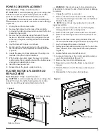
POWER CORD REPLACEMENT   . . . . . . . . . . . . . . . . . . . . . . . . . . . . . . . . . . . . . . . . . . 9

FLICKER MOTOR & FLICKER ROD REPLACEMENT

  . . . . . . . . . . . . . . . . . . . . . . . . . . 9

LED LIGHT ASSEMBLY REPLACEMENT . . . . . . . . . . . . . . . . . . . . . . . . . . . . . . . . . . . 10
LOG SET ASSEMBLY REPLACEMENT  . . . . . . . . . . . . . . . . . . . . . . . . . . . . . . . . . . . . 10

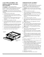
GLASS MEDIA ASSEMBLY AND PARTIALLY REFLECTIVE PANEL REPLACEMENT

 11

THERMISTOR REPLACEMENT  . . . . . . . . . . . . . . . . . . . . . . . . . . . . . . . . . . . . . . . . . . .11
TROUBLESHOOTING GUIDE . . . . . . . . . . . . . . . . . . . . . . . . . . . . . . . . . . . . . . . . . . . . 12

TABLE OF CONTENTS

Summary of Contents for DF2024

Page 1: ...America Limited Dimplex North America Limited 1367 Industrial Road Cambridge ON Canada N1R 7G8 1 888 346 7539 www dimplex com REV PCN DATE 00 11 JUL 14 01 14284 16 SEP 14 IMPORTANT SAFETY INFORMATION...

Page 2: ...se the user to the risk of fire serious injury or death OPERATION 3 MAINTENANCE 4 EXPLODED PARTS DIAGRAM 5 REPLACEMENT PARTS 5 WIRING DIAGRAM 6 SWITCHBOARD REPLACEMENT 7 RELAY BOARD REPLACEMENT 7 AC D...

Page 3: ...not occur again D E Thermostat Controls Adjusts the temperature set point to your individual require ments Once the desired set temperature is reached the heater will turn off The heater will cycle o...

Page 4: ...ds on the glass surface Compact Fireplace Surface Cleaning Use warm water only to clean painted surfaces of the Com pact Fireplace Do not use abrasive cleaners Servicing Except for the cleaning descri...

Page 5: ...rtially Reflective Panel 5902580100RP 7 Front Glass 5902570100RP 8 Felt Feet Pads Set of 4 8600140101RP 9 Log Set Assembly 0478550100RP 10 Glass Media 0441480100RP 11 Display Control Board 3001350300R...

Page 6: ...6 www dimplex com WIRING DIAGRAM 2 LED LIGHT HARNESS OR 3 LED LIGHT HARNESS POWER SUPPLY L N Thermistor Display Board Relay Board Switchboard N L...

Page 7: ...T Tools Required Phillips Head Screwdriver Flat Head Screwdriver Needle Nose Pliers CAUTION If unit was operating prior to servicing allow at least 10 minutes for lights heating elements and top panel...

Page 8: ...removing the retaining screws which secure the firebox brackets to the mantel 3 Remove the three screws along the back of the unit the two on either side along the top edge and the two at the top of t...

Page 9: ...Screwdriver CAUTION If unit was operating prior to servicing allow at least 10 minutes for lights heating elements and top panel to cool off to avoid accidental burning of skin WARNING Disconnect pow...

Page 10: ...ires the board to be removed This can be done by removing the two screws on the right hand side of the unit reaching between the partially reflective panel and the back of the unit to remove the displ...

Page 11: ...screws which secure the firebox brackets to the mantel 3 Remove the three screws along the back of the unit and the two on either side along the bottom edge Figure 6 4 Lay the Compact Fireplace on it...

Page 12: ...board 3001370100RP Defective display control board Replace the display control board 3001350300RP Defective relay board Replace the relay board 3001360100RP Defective AC DC adapter Replace the AC DC a...

Page 13: ...its an odor Normal Operation Normal operation is when the heater emits an odor for a brief period after the heater is initially turned on The heater is burning off any dust accumulated during manufact...

Reviews: