


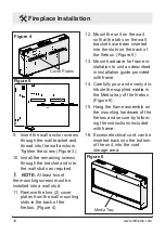


9
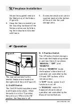
be installed in the appropriate
wall locations to fasten the wall
bracket through the remaining
holes. (Figure 2) For example, if
you plan to secure the bracket to
studs through holes A&D, install
anchors centered on holes B and
C.
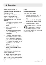
3.
Hold the wall-mounting
bracket on the wall and mark
the location of ONE (1) of the
mounting holes.
4. Place the bubble level onto
the top of the wall-mounting
bracket.
5.
Adjust the wall-mounting
bracket so the bubble on the
level is centered between the
two black lines.
6.
Mark three (3) other mounting
screw locations, on the wall,
ensuring that the wall bracket
stays level.
7.
Install the supplied wall
anchors on the drywall
marked locations by placing
a #2 Phillips screwdriver into
the recess of the anchor.
8. Press the anchor into the wall
in the desired marked position
while turning the anchor
clockwise until it is flush with
the wall.
CAUTION:
Ensure that the
top of the unit is at least
610mm (24") from the ceiling
or any object (i.e. Electrical
receptacles) that may obstruct
or be susceptible the flow or
temperature of air out of the
unit.
CAUTION:
High temperature,
keep electrical cords, drapery,
and other furnishings at least
3 ft (0.9m) from the front of the
heater and away from the side
and rear.
2. The wall-mounting bracket
must be mounted to at
least two (2) wall studs.
Studs should be accessed
through two (2) wall-bracket
holes in one of the following
combinations: A&F, B&D, or
C&E (Figure 1).
!
NOTE:
Wall anchors must
Fireplace Installation
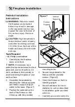
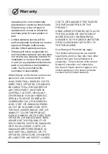
Wall anchor
Screw
Wall
bracket
Figure 3


