


3
walls). It is supplied with one of hundreds of independent
frequencies to prevent interference with other units.
!
NOTE:
Before attempting any operation with the
remote, pull the plastic insulator strip out from between
the remote casing and battery cover (Figure 2).
To operate, push the ON button sequence through the 3
levels of the fireplace (see manual controls for more detail),
push the OFF button to turn the fireplace off.
Remote Control Initialization/Reprogramming
If the remote control or remote control receiver has been
replaced, follow these steps to initialize the remote control
and receiver:
Ensure that power is supplied through main service
1.
panel.
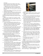
Access the manual controls, (remove glass doors or
2.
pull grill down if applicable) pull right hand edge of right
hand steel curtain towards the center of unit.
Locate manual controls. (Figure 1)
3.
Activate the On/Off switch, the red level 1 indicator light
4.
will flash.
Press and hold the “ - “ portion of the 3-position heater
5.
switch for five (5) seconds (the second red indicator
light will flash).
Press the On button located on the remote control.
6.
(Figure 2)
This will synchronize the remote control and receiver.
!
NOTE:
You will have only 10 seconds to perform this
last step. Failure to do so will result in these steps
needing to be followed again.
Battery Replacement
To replace the battery:
Slide battery cover open on the remote control (Figure
1.
2).
Install one (1) 12-Volt (A23) battery in the battery
2.
holder.
Close the battery cover
3.
Battery must be recycled or disposed of properly.
Check with your Local Authority or Retailer for
recycling advice in your area.
OPERATION
Manual Controls
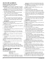
On/Off Switch
The On/Off Switch supplies power to the remote control
receiving unit. When placed in the On position Level 1
indicator will flash.
3-Position Heater Switch
Pressing “-” activates:
Level 1 (once) - the flame effect is turned on and the
first red indicator light is activated;
Level 2 (twice) - the flame effect remains on, the heater
is activated to the low heat setting, and the first and
second red indicator lights are activated;
Level 3 (three times) - the flame effect remains on, the
heater is set to the high heat setting, and all three red
indicator lights are activated.
Pressing “=” turns the fireplace off.
NOTE:
Hot air will blow from both sides of the fireplace
when the 3-position heater switch is activated. The heater
may emit a slight, harmless odor when first used. This odor
is a normal condition caused by initial heating of internal
heater parts and will not occur again.
Resetting the Temperature Cutoff Switch
Should the heater overheat, an automatic cut out will turn
the fireplace off and it will not come back on without being
reset. It can be reset by switching the On/Off Switch to Off
and waiting five (5) minutes before switching the unit back
on.
!
NOTE:
If operating the unit with a remote control, the
remote may require re-initializing after turning the power
off.
CAUTION:
If you need to continuously reset the heater,
disconnect power and call Dimplex customer service at
1-888-DIMPLEX (1-888-346-7539).
Remote Control
!
NOTE: This unit is not designed to be used with
wall switches for flame control, thermostat control or
Dimplex wall setters.
The fireplace is supplied with a radio frequency remote
control. This remote control has a range of approximately
50 feet (15.25 m), it does not have to be pointed at the
fireplace and can pass through most obstacles (including
Figure 2
Off Button
On
Button
Battery
Cover
Plastic
Strip
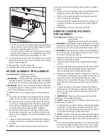
Figure 1
Manual Controls
3-Position
Switch
On/Off
Switch
Level 3 Indicator
Level 2 Indicator
Level 1 Indicator


