background image

Millbrook House, Grange Drive, Hedge End, Southampton, SO30 2DF

0844 879 3587

dimplex.co.uk | gdcgroup.co.uk

6

1.2  Important Safety Information

• 

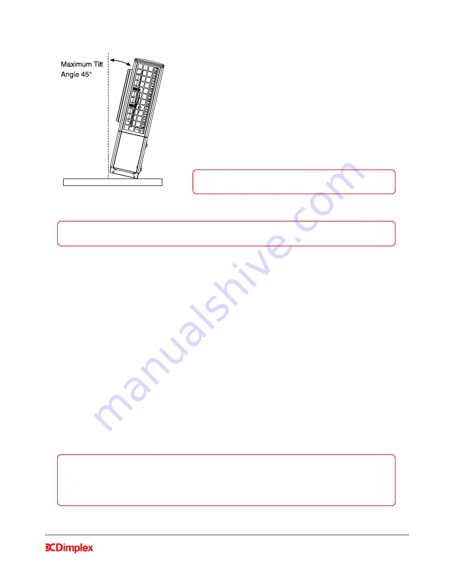
    Do not tilt the heat pump by more than 45° in any 

direction.

• 

    Do not lift without using correct lifting devices.

• 

    Ensure that all clearance dimensions are observed - this 

is important for correct heat pump operation and air flow.

• 

    Use a suitable lifting device in accordance with any 

relevant health and safety regulations.

• 

    Do not move or transport the heat pump flat.

WARNING: 

When using lifting rods to lift the heat pump, 

straps must also be used to prevent toppling.

Figure 1: Maximum tilt angle 

NOTE: 

Leaving a clear pathway for delivery will allow the heat pump to be delivered as close to the 

installation site as possible to minimize moving / lifting. 

•  Never use cleaning agents containing sand, soda, acid or chloride as these can damage surfaces 

/ components.

•  Do not use muddy or dirty water to fill the heating system. This can cause components to 

malfunction and poses a corrosion risk to the system.

•  If the heat pump may be disconnected from the power supply for long periods of time, or where 

power supplies are susceptible to failure, antifreeze must be added to the system. 

Example: Mono ethylene glycol at 25% volume to protect down to -14°C in a holiday home.

•  Use a suitable filtration protection system and a corrosive additive to prevent the formation of 

oxides or solids in the heat pump condenser.

•  This appliance can be used by children aged from 8 years and above and persons with reduced 

physical, sensory or mental capabilities or lack of experience and knowledge if they have been 

given supervision or instruction concerning use of the appliance in a safe way and understand 

the hazards involved. 

•  Children shall not play with the appliance.

•  Cleaning and user maintenance shall not be made by children without supervision. 

NOTE: 

The heat pump contains refrigerant at high pressure. 

Safety measures are in place to avoid system pressure build up; 
 
Stage 1: Pressure transducer stops compressor.  
Stage 2: Pressure switch switches heat pump off. All safety devices reset automatically. 

Summary of Contents for A12M

Page 1: ...A Class Heat Pumps A8M A12M A16M Installation Manual dimplex co uk 8 60472 0 Issue 1 07 ...

Page 2: ......

Page 3: ... 1 Temperature Control Devices 18 3 1 2 Space Heating Zones 19 3 1 3 Location of Wiring Centre 19 4 Installation 20 4 1 Important Plumbing Information 20 4 1 1 Pipe Sizing Information 22 4 1 2 Buffer tank 23 4 1 3 Adjusting the spring loaded by pass valve if fitted 23 4 1 4 Metering for the Domestic Renewable Heat Incentive UK 24 4 2 Electrical Information 25 4 2 5 Access to Electrical Connections...

Page 4: ...s 41 4 5 4 Defrost 41 4 5 5 Operating data 41 4 5 6 History 41 5 System Health Check Maintenance 42 5 1 Heat pump 42 5 2 Electrical 42 5 3 Hydraulics 42 5 4 Indoor settings 42 6 Appendices 43 6 1 44 6 2 Refrigeration cycle 45 6 3 Schematics Example 1 46 6 4 Schematics Example 2 47 6 5 Schematics 1 2 3 4 Space Heating Only 48 6 6 Schematics 5 6 7 8 Zone space heating DHW 49 6 7 Schematics 9 10 11 1...

Page 5: ...TE Retain this manual for information The instructions included in this manual are important for the correct installation and use of Dimplex A Class air source heat pumps Please ensure that you retain this manual for reference The specifications and information supplied in this manual may be subject to change without notice at the discretion of Dimplex All attempts have been made to ensure that th...

Page 6: ...an cause components to malfunction and poses a corrosion risk to the system If the heat pump may be disconnected from the power supply for long periods of time or where power supplies are susceptible to failure antifreeze must be added to the system Example Mono ethylene glycol at 25 volume to protect down to 14 C in a holiday home Use a suitable filtration protection system and a corrosive additi...

Page 7: ...must be installed in accordance with national wiring regulations The local wiring regulations should always be followed paying particular attention to the mixing of low voltage and extra low voltage cabling Ensure the incoming power supply and the distribution board are suitably rated Ensure that the regulations specified by the local electricity supplier have been adhered to All fuse rating and p...

Page 8: ...s the initial heat load may be higher than the design load 1 4 Legal The construction and design of the heat pump complies with all relevant EU directives see CE declaration of conformity in Appendices section When connecting the heat pump to the power supply the relevant EN and IEC standards must be adhered to Any further connection requirements stipulated by the network operation must also be ob...

Page 9: ...12 90 kW COP 2 20 1 75733 0 The refrigeration cycle is hermetically sealed Contains Kyoto Protocol defined fluorinated greenhouse gases All work to be carried out on this unit is to be carried out by a competent person Power Factor A 2W55 PHeating Air to Water Variable Speed Heat Pump Max Op Pressure Revision Single Phase 230V 50Hz 45 kW Δp Electrical Power Max PHeating A7W35 Heating Water EN14511 2...

Page 10: ...2 Space heating and Dimplex Standard Heat Pump Cylinder This pack should contain five boxes Heat Pump ACCHYPK Hydraulics Kit A contains all of the necessary hydraulic components Cylinder Cylinder Accessories Wiring Centre A separate wiring centre is required as the wiring centre is not built into the standard cylinder Pack 3 Space heating only This pack should contain three boxes Heat Pump ACSHYPK...

Page 11: ...lve 28mm comp fittings 1755750 5 Pump UPM GEO 25 85 180 1500mm cable 1755740 6 Isolation valves 1 swivel BSP to 28mm comp Flow 1755760 7 Isolation valves 1 swivel BSP to 28mm comp Return with strainer 1755770 13 2 x Circulation Pump Gate Valve 11 2 swivel to 28mm comp 2 x Washer 30 1x21x2mm 1756090 Dimplex A Class cylinder kit which includes 8 A Class cylinder with integrated buffer 9 Safety group...

Page 12: ... 4592624105 Hydraulics Kit A ACCHYPK 2 User interface UI 1754600 3 ERES spring loaded by pass valve 22mm comp fitting 1755780 4 3 port diverting valve 28mm comp fittings 1755750 5 Pump UPM GEO 25 85 180 1500mm cable 1755740 6 Isolation valves 1 swivel BSP to 28mm comp Flow 1755760 7 Isolation valves 1 swivel BSP to 28mm comp Return with strainer 1755770 12 2 x Circulation Pump Gate Valve 11 2 swiv...

Page 13: ...User interface UI 1754600 5 Pump UPM GEO 25 85 180 1500mm cable 1755740 6 Isolation valves 1 swivel BSP to 28mm comp Flow 1755760 7 Isolation valves 1 swivel BSP to 28mm comp Return with strainer 1755770 4 2 x Circulation Pump Gate Valve 11 2 swivel to 28mm comp 2 x Washer 30 1x21x2mm 1756090 Wiring centre module which includes 9 Wiring centre module 049162 11 1 x Temperature probe NTC10 for DHW A...

Page 14: ...with the latest version of MIS3005 for UK installations If a non A Class heat pump cylinder is being used ensure that it has been accurately sized with the appropriate coil surface area of the cylinder to match the heat pump s output and flow rate requirements and that all necessary hydraulic connections have been considered in connecting it to the heat pump system Ensure that suitable heat emitte...

Page 15: ...re 4 Poor air flow CAUTION Ensure that there are no obstructions in front of the heat pump fan for at least 1m however 2m is recommended ANY type of obstruction in front of the heat pump even small shrubs can block the air flow and cause cold air recirculation Figure 5 Good air flow with recommended clearances ...

Page 16: ...m x 500mm The concrete plinth must be able to withstand the unit s weight of 110 140kg depending on model A minimum distance of 50mm between the heat pump and the edge of the plinth is required on all sides CAUTION The minimum clearance distances around the heat pump are shown in figure 3 300mm at the rear for air flow 500mm each side for service and at least 1000mm in front of the fan to avoid ai...

Page 17: ...led and is running to a drain 2 Remove the heat pump panels to mark drilling holes on plinth The heat pump panels must be removed so that the base panel is visible To do this remove the screws and slide the panels downwards and out Once the panels are removed mark the holes for the fixing bolts figure 6 then lift or slide the heat pump out of the way to drill the holes Leave the panels off until a...

Page 18: ...nd fix in place using the M10 bolts supplied in the installation pack 5 Positioning and Fixing Indoor Components The controller and thermostats should be installed on internal walls in living area to reflect the correct room temperature and away from direct sunlight drafts windows and doors and heat emitters 3 1 1 Temperature Control Devices The controller user interface that is supplied with the ...

Page 19: ... additional optional feature of the heating system The standard package comes with one user interface and the possibility of four separate zones Each heating zone can be assigned a heat curve specific to the type of heat emitters 3 1 3 Location of Wiring Centre If a Dimplex A Class cylinder is used the wiring centre is built in to the A class cylinder and pre wired If a non A Class cylinder is use...

Page 20: ...mplex heat pump hydraulics pack This means that in order to clean the strainer the system does not have to be drained Instead it is possible just to close the isolation valves on the return and remove the strainer This way the only water that will be lost from the system is that between the non return valve and strainer The strainer must be fitted in order to prevent contamination of the condenser...

Page 21: ... and strainer The strainer must be fitted in order to prevent contamination of the condenser heat exchanger If an alternative strainer is used it must be at least 7 microns in size System should be pressurised and the system pressure must be checked once valves are re opened Direct condensate drain pipe to soak away or drain All piping must be properly insulated and external length kept to a minim...

Page 22: ...elivery for information A8M A12M A16M Space heating only DHW with A Class cylinder Water flow rate 1100 l h nominal 2100 l h nominal 1800 l h nominal Associated head available 60kPa 14kPa 18kPa Pipe diameter mm Internal diameter mm Maximum equivalent pipe length 90 N A N A 300 23 38 22 28 32 19 8 25 6 29 6 0 31 l m 0 51 l m 0 69 l m 600 46 77 Table 1 Maximum equivalent length for copper pipe water...

Page 23: ...d bypass must not be used and instead must be replaced by an open bypass fitted with a gate valve This is to ensure that the zone pump s is are not running against a dead head when the heat pump is idle or in DHW mode The bypass valve is used to maintain a minimum flow rate and prevents faulty operation of the heat pump as well as allowing it to run efficiently The bypass valve must be adjusted co...

Page 24: ...nd 175mm of straight pipework on the outlet pipe For installations using 28mm pipe please leave 560mm of straight pipework on the meter inlet pipe and 175mm of straight pipework on the outlet pipe Install low pressure drop isolation valves to avoid the need to drain systems when fitting heat meters See the schematics Appendices for more information on valve locations Leave sufficient pipework acce...

Page 25: ...ture probes or room thermostats are required for additional heating zones The wiring diagrams in the Appendices section show the different possible wiring configurations for systems with and without a Dimplex A Class cylinder WARNING Before opening the heat pump ensure all circuits are isolated WARNING Ensure that the components in the electrical box do not get wet when the electrical box is opene...

Page 26: ... can be opened by removing a screw to allow access to cables CAUTION Ensure that cable access covers are closed correctly when not in use CAUTION Follow steps in reverse order to close the heat pump When closing the heat pump front panel ensure that the top and bottom panels are interlocked 4 2 6 Electrical Connections power and Modbus cable heat pump connections The electrical connections to the ...

Page 27: ...ase of the heat pump see figure 11 Figure 11 Electrical cabling configuration 1 For configuration 2 the cables are fed through the holes at the back of the heat pump up through the holes in the base of the heat pump and then from outside the electrical box through the cable glands see figure 12 Figure 12 Electrical cabling configuration 2 M16X1 5 Cable Gland RS485 Modbus Cable M16 Lock Nut M25x1 5...

Page 28: ...t is recommended to connect the Modbus cable in daisy chain series as shown in figure 13 from the heat pump on to the wiring centre and then on to the UI The jumpers will be in the correct factory setting for this wiring configuration by default If using the recommended configuration the jumper position does not need to be changed Figure 13 Recommended MODBUS cable configuration If it is deemed ne...

Page 29: ...9 3587 dimplex co uk gdcgroup co uk 29 To replace the cover position the rotary dial over the holding pin on the board ensuring the two are lined up correctly Replace the cover and bottom screw Ensure that rotary dial is tested and working once cover has been replaced ...

Page 30: ...ted by the main menu or screensaver if the heat pump is idle use the Esc button to return to the main menu To access the Installer Menu you must select the information menu represented by the i icon on the main menu shown in figure 14 Use the rotary dial to select the Login option and to scroll through numbers from 0 999 Input the code to access the installer settings 22 then the code to bring up ...

Page 31: ...required 12 C and or the space heating return temperature is 18 C start by heating the buffer tank There is not currently a software function to close down the heating circuits so to do this the rest of the heating circuit must be closed down manually to allow the buffer tank to heat up well above 25 C Once this temperature has been achieved individual heating circuits i e zones can be opened grad...

Page 32: ...ey are both mono energy systems using an immersion heater two zones space heating and DHW functions The difference between examples 1 and 2 is that example 1 shows an example of a system requiring an open by pass while example 2 requires the installation of a spring by pass Table 4 Schematic codes information 1 0 0 0 3rd Digit 2 mono energy heat pump electric back up 3 bivalent heat pump with boil...

Page 33: ...ystem must be fully bled The expansion vessel must be fitted Membrane pressure of the expansion vessel must be checked and adjusted Figure 17 Waterside Check When checks are completed and Next is selected the type of temperature measurement devices to be used in each heating zone must also be selected by scrolling across and pressing confirm The following options are available User Interface usual...

Page 34: ... that should be made prior to commissioning for space heating The list is based on the schematic zone diagram selected and also the type of temperature devices that will be used in each zone Once you have confirmed all checks and select Next you will return to the commissioning menu where you can now access the Water flow check menu Figure 20 Electrical connections 4 4 6 Water Flow Check Select Ru...

Page 35: ... see message 1 or 2 this might be an indication of an air lock dirty strainer flow restriction or pump too small for the required pipework Please check for these issues and if present rectify to ensure that there is sufficient flow then repeat the test There will be a time delay before you can restart the test When you seea screen with the pump highlighted in green flow has been detected and the c...

Page 36: ...een filled When the cylinder is ready it will be necessary to return to this step of the commissioning and select Y instead for Cylinder Connected to set up domestic hot water 4 4 8 Electrical connections DHW This menu provides a list of electrical connections that should be made prior to commissioning the domestic hot water cylinder You must check and confirm all connections in order to make the ...

Page 37: ...inders the Finish button figure 29 can be used before 60 C temperature has been reached as the compatibility doesn t have to be proven Once the DWH cylinder is showing signs of being heated up then the Finish function allows to shorten the DHW test without having to wait until temperature achieves 60 C This Finish function should be used in cold humid conditions to avoid defrost issues defrost is ...

Page 38: ...y the test failed and advice on checks to carry out If the test is complete and has been successful you will see the screen shown on the right in figure 30 which shows the maximum temperature that the cylinder can achieve 4 4 10 Disinfection thermal Thermal disinfection is a function which keeps the level of legionella bacteria in the cylinder under acceptable levels This is carried out by heating...

Page 39: ... This will bring you to a default heating curve for the selected emitter Selecting Next will select the default The pre defined curves have recommended temperature ranges for each heat emitter Table 5 Heating Curve Parameters The values that generate the heating curve graph can be changed by scrolling through the temperature value to adjust and setting it This is validated using the Set button whe...

Page 40: ...carried out successfully you will see the screen shown in figure 33 Figure 33 Setup complete Selecting Auto will activate all settings where as selecting Off will enable the heat pump only to carry out frost protection i e no heating is required but the heat pump is protected from freezing conditions The default setting for the heat pump is Off To turn on the heat pump you must return to the home ...

Page 41: ...s Space Heating are confirmed The relays which control the immersion and backup heater buffer use an electric interlocking system and therefore R7 and R8 must be used together in order for the backup heater to function Testing these relays individually will not reflect this Figure 35 Output tests 4 5 4 Defrost Before running a manual defrost cycle you must ensure the buffer has been isolated from ...

Page 42: ...nels secure 5 2 Electrical Is the power cable firmly fixed Is the earth wire connection secure Is the supply voltage correct 5 3 Hydraulics Is the system correctly pressurized Are there any water leaks in the system Is the required pressure holding Is the strainer on the return pipe clear of debris See section 4 1 3 for details on isolating and cleaning the strainer 5 4 Indoor settings Are the set...

Page 43: ... Space Heating Only 6 6 Schematics 5 6 7 8 Zone Space Heating Domestic Hot Water 6 7 Schematics 9 10 11 12 Bivalent Space Heating 6 8 Schematics 13 14 15 16 Bivalent Zone Space Heating Domestic Hot Water 6 9 Wiring Centre Electrical Connections with A Class Cylinder 6 10 Jumper Information for Alternative Wiring Configuration 6 11 Controller Cable Connections 6 12 Installer Menu Flow Chart 6 13 In...

Page 44: ...nst wall dB A 41 5 38 5 38 5 3 5 Heating Water Flow Rate A7W35 nominal minimum m h 1 15 0 85 2 1 1 2 2 1 1 2 3 6 Condenser Pressure Drop nominal flow rate A7W35 kPa 3 4 4 3 7 Air Flow A7W35 m h 2600 3700 3700 3 8 Refrigerant total filling weight Type kg R410A 1 75 R410A 2 0 R410A 2 0 3 9 Water Capacity of Stainless Steel Heat Exchanger litre 0 85 1 1 3 10 Polyol Ester Oil in Compressor 8 1 1 e r t...

Page 45: ... dryer 9 Electronic expansion valve 10 EVI Economizer 11 EVI pressure transducer 12 Inverter 13 High pressure switch 14 Service valve 15 High pressure transducer 16 Low pressure transducer T1 Coil temp T2 External air temp T3 Flow temp T4 Return temp T5 Compressor suction temp T6 Vapor injection temp T7 Liquid line temp 1 2 3 4 5 6 7 8 9 10 12 14 9 7 14 16 15 13 Ø10 Ø18 Ø12 Ø12 Ø18 Ø12 Ø10 REFRIGE...

Page 46: ...flow adjustment on open by pass If multiple heat emitter circuits are installed operating at different flow and return temperatures such as under floor heating and standard radiators a mixing valve must be used on low temperature circuits to prevent high temperature water from entering the under floor heating manifold See Note Note NOTE If ANY of the zones are using an externally controlled circul...

Page 47: ...E Isolation switch may be 20 Amp for 8kW heat pumps or 40 Amp for 12 16kW heat pumps Zone Valve NOTE Please ensure that the heat pump circulation pump is correctly sized for the installation e g minimum flow is maintained through heat pump at all times Zone Valve Zone 1 Room Thermostat T NOTE Fill Flush connections are not supplied by Dimplex and must be sourced separately T T Normally Open Exampl...

Page 48: ...nical T stat User Interface or NTC10 or Mechanical T stat User Interface or NTC10 or Mechanical T stat 20Amp Isolation Switch E N L L N E See example 1 or 2 for by pass options For details of different types of zone set up with without circulating pump see example schematics Isolation switch may be 20Amp for 8kW heat pumps or 40 Amp for 12 16kW heat pumps NOTE Fill Flush connections are not suppli...

Page 49: ...nterface or NTC10 or Mechanical T stat Max 1 Meter Isolation Switch 6mm 6mm 6mm E N L L N E For details of different types of zone set up with without circulating pump see example schematics See example 1 or 2 for by pass options Isolation switch may be 20Amp for 8kW heat pumps or 40 Amp for 12 16kW heat pumps NOTE Fill Flush connections are not supplied by Dimplex and must be sourced separately S...

Page 50: ...C10 Mechanical Thermostat if UI Controller NOT used Zone 1 Room Thermostat Back Up Heater E N L L N E See examples 1 or 2 for by pass options Expansion Valve Depending on system volume For details of different types of zone set up with without circulating pump see example schematics Isolation switch may be 20Amp for 8kW heat pumps or 40 Amp for 12 16kW heat pumps 20Amp Isolation Switch NOTE Fill F...

Page 51: ...y Single Phase 230 240V 50Hz Mains Supply Single Phase 230 240V 50Hz Heater 20Amp Isolation Switch E N L L N E See example 1 or 2 for by pass options Isolation switch may be 20Amp for 8kW heat pumps or 40 Amp for 12 16kW heat pumps For details of different types of zone set up with without circulating pump see example schematics NOTE Fill Flush connections are not supplied by Dimplex and must be s...

Page 52: ...C ZONES SEE CONTROLLER CABLE CONNECTIONS DIAGRAM FOR DETAILS Buffer Immersion 3kW DHW SH Valve WHITE blue EARTH SHIELD WHITE Orange BLUE white CONNECTIONS ARE LOCATED INSIDE THE UI CASING SEE BELOW WHITE orange ORANGE white BLUE white WHITE blue EARTH SHIELD GND 12V A B S CONNECTIONS ARE LOCATED INSIDE THE ELECTRICAL BO IN THE HEAT PUMP N P SH Zone 2 Valve L N P SH Zone 3 Valve L N P S B A 0V 230V...

Page 53: ... WHITE Orange BLUE white CONNECTIONS ARE LOCATED INSIDE THE UI CASING SEE BELOW WHITE orange ORANGE white BLUE white WHITE blue EARTH SHIELD GND 12V A B S CONNECTIONS ARE LOCATED INSIDE THE ELECTRICAL BOX IN THE HEAT PUMP N P SH Zone 2 Valve L N P SH Zone 3 Valve L N P S B A 0V 230V SUPPLY L N P L N P PWM Control Cable not used L N P L NOTE DIGITAL INPUTS DI01 DI05 ARE VOLT FREE IF ANY VOLTAGE SUC...

Page 54: ...r ON NOTE The diagram above shows the ON OFF positions of jumpers for the recommended configuration NOTE The alternative wiring configuration is shown below but should only be used if absolutely necessary Wiring centre electrical configurations with A Class cylinder Figure 36 Jumper in ON position on SEC board Figure 37 Jumper in OFF position on water module Figure 38 Jumper in ON position on user...

Page 55: ...Millbrook House Grange Drive Hedge End Southampton SO30 2DF 0844 879 3587 dimplex co uk gdcgroup co uk 55 6 12 Controller cable connections ...

Page 56: ... Electrical Connections DHW Waterflow Checks Language Selection Commissioning General Schematic Waterside Checks Message List History Electrical Connections Space Heating Only Operating Data Input Output Tests Disinfection Heating Zone Selection Heating Circuit Type Setup Complete ON Automatic 6 13 Installer menu flow chart ...

Page 57: ...odel Heat Pump Serial No Cylinder Model Cylinder Serial No Accessories Installed Schematic No Used in Commissioning Temperature Devices Used for Zone Control Zone 1 Zone 2 Zone 3 Zone 4 Heat Emitters Installed Temperatures Recorded at Commissioning Flow Temperature C Return Temperature C Outside Temperature C Spread K Flow Rate m3 h Refrigeration High Pressure Low Pressure Heat Exchanger Temp Refr...

Page 58: ...tive 2006 95 EC EMC directive 2004 108 EC Pressure equipment directive 97 23 EC Applied Standards EN 60335 1 2002 A11 A1 A12 corr A2 2006 EN60335 1 A13 2008 EN60335 2 40 2003 A11 A12 A1 corr A2 2009 EN55014 1 2006 EN55014 2 1997 A1 2001 EN61000 3 2 2006 EN61000 3 3 1995 A1 2001 A2 2005 EN378 1 2008 EN378 2 2008 A1 2009 EN378 3 2008 EN378 4 2008 EN 14511 1 2007 EN14511 2 2007 EN14511 3 2007 EN14511...

Page 59: ...Millbrook House Grange Drive Hedge End Southampton SO30 2DF 0844 879 3587 dimplex co uk gdcgroup co uk 59 ...

Reviews: