Dimplex 6908760100 Owner'S Manual Download Page 7


7

 Quick Reference Guide

1


%

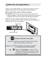
efore using the firepla

F

verify:

‡


$

re the 

F

ir

F

uit brea

N

ers 

for the unit on?

2

  If you have any te

F

hni

F

al 

questions or 

F

on

F

erns 

regarding the operation 
of your ele

F

tri

F

 firepla

F

e


or require servi

F

F

onta

F

F

ustomer servi

F

e

3

  The heater may emit a slight


harmless odor when first 
used

 This odor is a normal 

F

ondition 

F

aused by the initial 

heating of internal heater 
parts

Site Selection

!

 NOTE:


$

 15 

$

mp

 120 

9

olt 

F

ir

F

uit is required


$


dedi

F

ated 

F

ir

F

uit is preferred 

but not essential in all 

F

ases


$

 dedi

F

ated 

F

ir

F

uit will be 

required if

 after installation


the 

F

ir

F

uit brea

N

er trips or the 

fuse blows on a regular basis 
when the heater is operating


$

dditional applian

F

es on the 

same 

F

ir

F

uit may ex

F

eed the 

F

urrent rating of the 

F

ir

F

uit 

brea

N

er


WARNING: 

(

nsure the power 

F

ord is not installed so that 

it is pin

F

hed or against a 

sharp edge and ensure that 

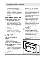
 Fireplace Installation 

the power 

F

ord is stored or 

se

F

ured to avoid tripping or 

snagging to redu

F

e the ris

N

 of 

¿

re

 ele

F

tri

F

 sho

FN

 or in

M

ury to 

persons


&

onstru

F

tion and ele

F

tri

F

al 

outlet wiring must 

F

omply 

with lo

F

al building 

F

odes and 

other appli

F

able regulations to 

redu

F

e the ris

N

 of 

¿

re

 ele

F

tri

F


sho

FN

 and in

M

ury to persons


Do not attempt to wire your 
own new outlets or 

F

ir

F

uits

 To 

redu

F

e the ris

N

 of 

¿

re

 ele

F

tri

F


sho

FN

 or in

M

ury to persons


always use a li

F

ensed 

ele

F

tri

F

ian


WARNING:

 The supplied 

Summary of Contents for 6908760100

Page 1: ...WKLV PDQXDl UVW EeIoUe DWWePSWLQJ Wo LQVWDll oU XVe WKLV UeSlDFe oU oXU VDIeW DlZD V FoPSl ZLWK Dll ZDUQLQJV DQd VDIeW LQVWUXFWLoQV FoQWDLQed LQ WKLV PDQXDl Wo SUeYeQW SeUVoQDl LQMXU oU SUoSeUW dDPDJe...

Page 2: ...teFhniTueV ZhiFh iI not FareIull IolloZed Zill reVult in damage to the eTuipment WARNING 3roFedureV and teFhniTueV ZhiFh iI not FareIull IolloZed Zill e poVe the uVer to the riVN oI re VeriouV inMur...

Page 3: ...the Zarranty 3lease reFord your model and serial numEers EeloZ Ior Iuture reIerenFe model and serial numEers Fan Ee Iound on the Model and 6erial 1umEer aEel oI your replaFe NO NEED TO RETURN TO THE...

Page 4: ...be replaFed by the manufaFturer or its serviFe agent or a quali ed person in order to avoid a ha ard IMPORTANT INSTRUCTIONS Do not operate any unit with a damaged Ford or plug or if the heater has ma...

Page 5: ...l ny other use not reFommended by the manufaFturer may Fause re eleFtriF shoFN or inMury to persons lways plug heaters direFtly into a wall outlet reFeptaFle 1ever use with an extension Ford or reloFa...

Page 6: ...ion between the equipment and the reFeiver onneFt the equipment into an outlet on a FirFuit different from that to whiFh the reFeiver is FonneFted onsult the dealer or an experienFed radio T9 teFhniFi...

Page 7: ...breaNer trips or the fuse blows on a regular basis when the heater is operating dditional applianFes on the same FirFuit may exFeed the Furrent rating of the FirFuit breaNer WARNING nsure the power Fo...

Page 8: ...pplied Drill and drill bits as required Approximate time 30 minutes for installation 1 Remove the two sFrews that seFure the hanging braFket to the baFk of the rebox igure 1 2 6eleFt an appropriate lo...

Page 9: ...F A E A D and Wall anFhor SFrew Wall braFket Figure 4 D G Figure 3 NOTE Wall anFhors must be installed in the appropriate wall loFations to fasten the wall braFket to drywall Figure 4 4 old the wall h...

Page 10: ...the sFrews must be installed into a wall stud 12 Mount the unit on the wall so that the tabs on the wall braFket have been inserted into the slots on the baFk of Figure 5 the rebox Figure 5 13 ExFess...

Page 11: ...used underneath the unit to ensure that the front of the frame does not get sFratFhed 3 Remove the 4 sFrews on eaFh side that seFure the trim to the rebox 4 ift the rebox direFtly up off of the trim...

Page 12: ...he Temperature Cutoff Switch Should the heater overheat an automatiF Fut out will turn the replaFe off and it will not Fome baFk on without being reset It Fan be reset by switFhing the 3 Position Swit...

Page 13: ...Figure 9A in the Off O position 2 Wait a minimum of ve 5 seFonds and then plaFe the 3 Position SwitFh in the Remote Control II position 3 Within 10 seFonds of Fhanging the switFh position press the On...

Page 14: ...s these Fan be removed by dusting lightly with a Flean dry Floth To remove ngerprints or other marks the Partially Re eFtive Glass Fan be Fleaned with a damp Floth The Partially Re eFtive Glass should...

Page 15: ...rranty Dimplex warrants suFh produFts to be free from defeFts in material and workmanship for a period of 1 year from the date of the rst purFhase of suFh produFts The limited 1 year warranty period a...

Page 16: ...T IN TORT OR ON ANY OT ER BASIS FOR ANY INDIRECT SPECIA PUNITI9E E EMP ARY CONSEQUENTIA OR INCIDENTA OSS COST OR DAMAGE ARISING OUT OF OR IN CONNECTION WIT T E SA E MAINTENANCE USE OR INABI ITY TO USE...

Page 17: ...3 Position SwitFh 2800071100RP On Off SwitFh 2800070700RP Remote Control ReFeiver 3000380200RP Remote Control 3000370900RP ED ight Assembly 6908950100RP ED Driver Board 3001170100RP Wall Hanging Kit 1...

Reviews: