12
6.8 Ducting Installation
14. Slot the Ø80 PVC elbow into the appliance’s air outlet,
and the insulated elbow into the air inlet.
15. Put the cover parts back onto the insulated elbow.
When installing the air ducting ensure the Edel is situated
on the tripod provided and note the correct positions for
installing the air connections as illustrated in Figure 9.
Dimplex offer a basic vent kit is provided with the prod
-
uct to accommodate installations as per 6.8.1 and 6.8.2.
Should it be necessary to install the product further away
from the nearest outside wall the vent extension kit is
required. The extension vent kit part number is noted on
Section 8.7.
NOTE: For installations with longer air duct
runs, the total pressure drop must be
considered and the ducting components
sourced and installed correctly by the
installer.
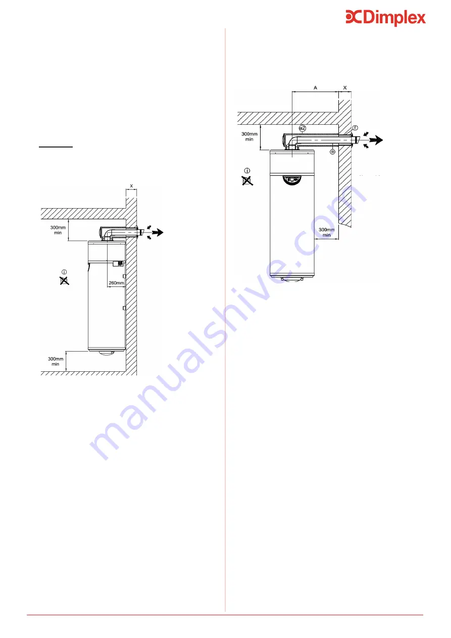
Figure 11: Offset access installation
6.8.1 Direct access
Ambient air
or
Exterior air
6.8.2 Offset access
Figure 10: Direct access installation
Ambient air
or
Exterior air
Installation
1. Cut the Ø125 PVC pipe to (X + 25 mm), X is the di-
mension reference in Figure 10.
2. Glue the pipe into the opening in the wall.
3. Position the Ø125 wall joint terminal.
4. Pass the assembled air duct nozzle through the wall
from the outside.
5. Direct the air duct nozzle upwards as indicated on
the diagram to ensure rain or moisture do not enter the
nozzle.
6. The Ø125 PVC pipe should overlap by about 25mm on
the inside wall.
7. Mark the direction of the air duct nozzle on the inside
by marking the top of the Ø125 PVC pipe.
8. Glue the wall flange onto the Ø125 PVC pipe, and
pressing it against the inside wall at the same time.
9. Cut the Ø80 PVC pipe to (X + 225mm).
10. Remove the cover parts from the insulated elbow
(length 355mm).
11. Insert the Ø80 PVC elbow into the base of the insu-
lated elbow and affix it to the Ø80 PVC pipe (apply a bit
of silicone so that the assembly stays put together).
12. Fix the other end of the Ø80 PVC elbow into the air
duct nozzle.
13. The insulated elbow should be fixed into the wall
flange at the same time.
1. Cut the Ø125 PVC pipe (rep.f) to (X + 25mm).
2. Glue it into the air duct nozzle.
3. Position the Ø125 wall joint.
4. Pass the assembled air duct nozzle through the wall
from the outside.
5. Direct the air duct nozzle upwards as indicated on the
diagram.
6. The Ø125PVC pipe should overlap by about 25mm on
the inside.
7. Mark the direction of the air duct nozzle on the inside
by marking the top of the Ø125 pipe.
8. Glue the wall flange onto the Ø125 pipe while pressing
it against the wall at the same time.
9. Cut the Ø80 PVC pipe to (A + X - 30mm).
10. Cut the insulated air duct to (A-205mm).
11. Cut the insulated elbow (length 975mm) to (A -5mm).
12. Remove the cover parts from the insulated elbow.
13. Insert the Ø80 PVC elbow into the base of the insu-
lated elbow and fix it to the Ø80 PVC pipe (apply a bit of
silicone so that the assembly stays put together).
14. Fix the other end of the Ø80 pipe into the air duct
nozzle. The insulated elbow should be fixed into the wall
flange at the same time.
15. Slot the Ø80 PVC elbow into the appliance’s air outlet,
and the insulated elbow into the air inlet.
16. Replace the cover parts back onto the insulated elbow.


