background image


10 

5.  GETTING READY TO PROFILE  


A. 

Place of installation 

 
The DIPRO P4600 profiling machine can be used both in a workshop and on site.  


Do not expose your machine to the effects of weather


B. 

Power 

 
The power supply is directly on the 220 V, 50 Hz network as standard single phase. (References 084746)


Operation on a 110V network requires the purchase of a specific model. (References 084745) 
This machine must be supplied by a transformer with the following specification: 

min 3 kVA (1650 VA Continuous)


Very  important:  the  electrical  line  intended  to  supply  the  machine  must  comply 
with the standards in force and in particular be protected by a 30 mA  differential 
circuit breaker 


C.


SPACE NEEDED


If working from a coil, the coil must be positioned at least 2 meters from the guides of the profiling machine. For the direction of 
insertion of the sheet into the machine (marking on the upper or lower face), you must refer to the suppliers’ recommendations. It 
must be ensured that the metal strip is aligned with the entry of the machine and that no constraint disturbs its unrolling.


Do not forget to service your machine (see "Maintenance" on pages 15).


Depending  on  the  material,  deformations  may  occur,  which  are  not  caused  by  the  roll-forming  but  by  the 
improper installation of the profiling machine. 

It is recommended to install a conveyor at the exit of the profiling machine to receive the trays.


Keep your workspace tidy:  

A messy workspace causes accidents and reduces your freedom of movement. 


D.


Handling of consumables


The metal sheets should not be profiled at too low a temperature (

no less than 7°C for zinc

). 

EN

G


2m 

EN

G


Summary of Contents for 084745

Page 1: ...EN G EN G DIPRO P4600 Standing seam profiling machine Ref 220V 084746 Ref 110V 084745 EN G ...

Page 2: ...2 ...

Page 3: ...ling of consumables 10 6 Please read before use 11 7 PREPARING FOR PROFILING 12 8 PROFILING 13 A Start up 13 B Removing the tray 13 C Reverse function 13 9 TRAY WITH SIDES HAVING UNEQUAL LENGTHS 13 10 Profiling in two passes 14 11 ADJUSTING THE PROFILING MACHINE 15 12 MAINTENANCE 16 A General guidelines 16 B List of wearing parts 16 C Maintenance to be performed regularly 16 13 Handling 17 A Wheel...

Page 4: ...4 ...

Page 5: ...ommend that you only use the accessories and materials listed in this manual This DIMOS electrical equipment is guaranteed for 12 months from the date of purchase against any manufacturing defect The purchase date chosen is that written on the invoice by the distributor sent to the end customer CUSTOMER AFTER SALES SERVICE TEL FAX E MAIL 33 0 2 40 83 25 01 33 0 2 40 83 88 12 sav dimos fr In order ...

Page 6: ...ard H24 Up to 0 80 mm Copper 1 4 hard Up to 0 80 mm Stainless steel 470 N mm2 Up to 0 50 mm Zinc Up to 0 80 mm Mini length 800 mm Profiling with 1 pass min width 235 mm Profiling with 1 pass min width 700 mm Profiling with 2 pass min width 130 mm Profiling with 2 pass min width 650 mm Please check the electrical supply is reliable and constant Read the instructions guide before use Read the genera...

Page 7: ... production Problems may occur during crimping if the dimensions are not respected C Type of tray The profiles are generally performed in a single operation when for example manufacturing Profile No 1 parallel trays Underclock Overclock Parallel tray 1 pass Conical tray 2 passes Inclined tray 1 pass EN G ...

Page 8: ...ay width approximately 78 mm appears when profiling a standard tray Example Width of the sheet metal strip 650 mm 1 Width at bottom of tray 572 mm 2 4 DESCRIPTION A Overview A1 Input guide A2 Control panel Power supply A3 Width fastening lever A4 Entry guide locking bolts 650 572 1 2 EN G A1 A2 A3 A4 ...

Page 9: ...1 Starting the profiling train Forward with auto hold function Reverse O Stop C2 Stop Emergency stop 1 pressure Stops all operating modes of the Profiling machine Prevents startup if engaged Clockwise rotation Reset C1 C2 ...

Page 10: ...oil the coil must be positioned at least 2 meters from the guides of the profiling machine For the direction of insertion of the sheet into the machine marking on the upper or lower face you must refer to the suppliers recommendations It must be ensured that the metal strip is aligned with the entry of the machine and that no constraint disturbs its unrolling Do not forget to service your machine ...

Page 11: ...e to profile sheet metal at temperatures below 7 C To profile several sheets of metal at once To profile sheet metal with cutouts To use reverse to unroll a tray This would damage the machine To use the machine without safety equipement gloves safety shoes etc IMPORTANT The manufacturer shall assume no responsibility for the consequences arising from the use or installation of the equipment not pr...

Page 12: ...the width of the inlet guides to the width of the sheet metal strip Use the clamping handle A3 to lock the train in position The material must be able to slide between the guides without any lateral movement Too tightly adjusted Sheet jams Adjusted with too much give Imprecise profiling Be sure to tighten the A3 handle sufficiently to avoid any inadvertent movement of the bank during the roll form...

Page 13: ...tal or at the front profiled Restart the roll forming machine until the profile is completely extracted using the C1 switch Support the tray on the exit and remove from the machine manually C Reverse function Using reverse gear can reposition a poorly set sheet On the control panel check that Stop Emergency stop C2 not initiated Flip switch C1 on to push the sheet back The machine will stop as soo...

Page 14: ... of the sheet metal The width of the input sheet guides must be adapted so that only one of the profiling trains forms the sheet The second train turns freely Slide the moving bank fully out Beware of the risk of collision if the machine is not open enough When profiling the sheet must be held correctly to obtain a good profile EN G ...

Page 15: ...w screw C to move the part to the desired value Tighten the screw B to bring it back into contact Tighten A screws To reduce the dimensions Unscrew A screws Tighten screw C to create some give to adjust Tighten screw B to move the part to the desired value Unscrew screw C to bring it back into contact Unscrew A screws Carefully check the height of the profiles and constantly check these dimensions...

Page 16: ...imal maintenance The drives are greased for life therefore only mechanical gearboxes are to be serviced periodically namely greasing the sprockets and drive chains of the tensioners retighten the motor chains if necessary In case of interventions on construction sites the machine must be protected against corrosion before and after the work spraying bare parts Furthermore the machine must be prote...

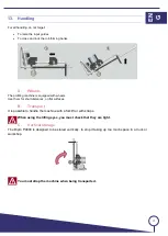
Page 17: ...se them for short distances on flat surfaces B Transport It is possible to handle the machine with a forklift or with straps When using the lifting eyes you must check that they are tight C Vertical storage The Dipro P4600 is designed to be stored vertically to stop it taking up too much space in a truck or workshop You must strap the machine when being transported EN G ...

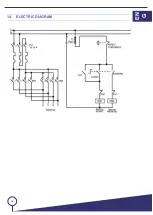
Page 18: ...18 14 ELECTRIC DIAGRAM EN G ...

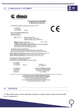
Page 19: ... 19 15 COMPLIANCE STATEMENT 16 DISPOSAL The Dipro 4600 does not contain hazardous materials or anything which requires special treatment when it is disposed of EN G ...

Page 20: ...20 ...

Reviews: