background image

FUJIFILM Dimatix, Inc. Confidential Information

Doc. # PM000040 Rev. 01

  March 26, 2008

Chapter

 10

Print Quality Troubleshooting

Printhead jetting issues and subsequent print quality issues typically fall into four main 
categories. This section shows the most likely causes, the resulting print artifact and 
corrective action that can be taken to mitigate the effects. 

1.0

Misdirected Nozzles

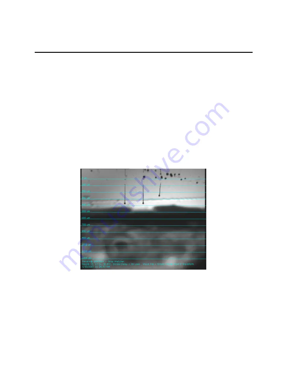
Misdirected nozzles refers to drops that are traveling off axis from left to right, or more 
difficult to resolve is front to back. The following figure illustrates a jet ejection off axis in 
the drop watcher.

Figure 10 - 1 Jets firing off axis

The primary causes of misdirected nozzles are contamination at or on the nozzle plate and 
or air inside the nozzle descender. Contamination is typically a static condition, meaning 
that the drop consistently jets to the side in spite of repeated cleaning cycles. This 
indicates that debris is lodged just inside the nozzle and is forcing the drop to eject at an 
angle. 

Summary of Contents for DMP-2800 Series

Page 1: ...Dimatix Materials Printer DMP 2800 Series User Manual Dimatix Materials Printer...

Page 2: ...ult in damage to the product economic loss personal injury or death Dieses Symbol kennzeichnet Hinweise zu Handlungsweisen Methoden oder Zust nden die zu Sch den am Produkt wirtschftlichem Verlu t Per...

Page 3: ...product 2 0 Important Safety Information Wichtige Sicherheitshinweise 2 1 Safety Sicherheit This symbol identifies parts that should be reclaimed as part of the Waste Electrical and Electronic Equipm...

Page 4: ...t vorgenommen werden Nur qualifiziertes Servicepersonal sollte die Abdeckungen am Produkt entfernen WARNING For continued protection against fire replace the line fuses only with fuses of the specifie...

Page 5: ...eine geerdete Steckdose gesteckt werden Benutzten sie nur dreiadrige Verl ngerungskabel mit Erdung WARNING For Dimatix Materials Printer DMP 2800 serial numbers less than 2831 0646 XXXX XXXXXXXXX Flu...

Page 6: ...e for reactions to occur in the absorbent pads where multiple and or incompatible fluids may come in contact with each other Vorsicht ist beim Umgang und Druck mehrerer verschiedener Fl ssigkeiten geb...

Page 7: ...rtridge Einstellungen m ssen sehr sorgf ltig gew hlt werden wenn mit leicht fl chtigen Materialien im Cartridge gearbeitet wird IMPORTANT IMPORTANT All moving parts are interlocked to the printer lid...

Page 8: ...will be required to correct the interference at one s own expense Note This product complies with the radio interference requirements of the European Union IMPORTANT IMPORTANT This product complies wi...

Page 9: ...rtant iii Notes iii Important Safety Information Wichtige Sicherheitshinweise iii Safety Sicherheit iii Important Wichtig vii Chapter 1 Introduction System Accessories 2 System Requirements 2 System I...

Page 10: ...Controls 30 Non Jetting Waveform 31 Jetting Waveform vs Non Jetting Waveform 31 Replacing Cleaning Pad 31 Chapter 5 Pattern Printing Select Pattern 35 Pre Defined Standard Patterns 36 Create Your Own...

Page 11: ...ties 92 Voltage vs Drop Mass 93 Chapter 8 Waveform Basics Waveform editor window explanation 96 Chapter 9 Cartridge Fluid Module Filling 102 Fill Syringe 102 Assembly 104 Attach Fluid Module to Jettin...

Page 12: ...n March 26 2008 Faults 117 System Diagnostics 119 Preventative Maintenance 121 Carriage 121 Reference Information 122 Appendix A Specifications System Description 123 Mechanical System 123 Cartridge 1...

Page 13: ...proof of concept and development work using ink jet technology It does have extensive capabilities to allow increased experimental sophistication to optimize process parameters for the user s applica...

Page 14: ...odel fluid 1 fill tip 1 cleaning pad 1 drop watcher pad 1 filter and 1 syringe Syringes Filters Fill tips Drop watcher pads Cleaning pads Substrate location and positioning system fiducial camera syst...

Page 15: ...3 FUJIFILM Dimatix Inc Confidential Information Doc PM000040 Rev 01 March 26 2008 Figure 1 1 DMP 2800 Lid Lid Closed Sensor Print Carriage Maintenance Station Blotting Pad Power Switch Indicator Ligh...

Page 16: ...hows the major components of the DMP Printer Carriage Figure 1 2 Print Carriage Fiducial Camera Cartridge Cable Skew Plate Holder Latch Cartridge Holder Print Carriage Fiducial Camera Cartridge Cable...

Page 17: ...nimum two people are required to lift it out of the crate and place it onto a surface sturdy enough to support it without excessive vibrations or oscillations Be careful not to put fingers into fan co...

Page 18: ...pattern for proper ventilation Figure 2 2 DMP air flow 4 Remove shrink wrap from DMP 5 Free items that have been secured for shipping Figure 2 3 DMP Packing material locations a Remove packing materi...

Page 19: ...2 Check back of the DMP for USB S video and power connections Identify appropriate cables 3 Connect all cables a Power cables to DMP PC and monitor b USB cable from PC to DMP c S video cable from DMP...

Page 20: ...Figure 2 5 DMP and PC cabling 2 0 PC Start up 1 Turn on power to PC 2 Allow PC to go through complete start up 3 0 Starting Your DMP 1 Make sure DMP lid is closed and all shipping foam is removed CAU...

Page 21: ...er to DMP a The light next to the power switch should go on Figure 2 6 DMP Indicator light b Wait at least 5 seconds 4 0 Dimatix Drop Manager 1 The DMP 2800 icon is on the PC desktop 2 Select the DMP...

Page 22: ...llation Doc PM000040 Rev 01 FUJIFILM Dimatix Inc Confidential Information March 26 2008 4 After initiating the program click OK to allow the DMP to run through its initialization sequence Figure 2 8 D...

Page 23: ...p Operation 1 0 Install Cartridge The following steps tell you how to install the Dimatix Model Fluid Cartridge Figure 3 1 Install cartridge Open Lid 1 Prepare the Dimatix Model Fluid Cartridge from t...

Page 24: ...holder on the carriage with the electrical connection pads towards the back of the machine matching the connector of the holder There is only one way for it to fit Push it down firmly so that it clic...

Page 25: ...tridge 5 After the cartridge is installed close the lid You should hear a pump turn on to control the meniscus pressure 6 The following window displays Figure 3 4 Confirm load cartridge settings windo...

Page 26: ...The Select Pattern window lets you select a pattern for printing Figure 3 5 Select Pattern screen 1 The Dimatix test pattern is auto selected This is a general use pattern which lets you see that the...

Page 27: ...mation Doc PM000040 Rev 01 March 17 2008 3 0 Load Unload Substrate The Load Unload Substrate tab is where you set the platen temperature and vacuum It is also where you must enter the thickness for th...

Page 28: ...ubstrate on the platen turn on the platen vacuum by selecting the Vacuum On button If your substrate is not very flat stiff or smaller than the platen you may need to cover some of the open vacuum hol...

Page 29: ...Up screen summarizes the previously made selections This screen displays the Print Pattern the Substrate Settings and the Cartridge Settings Figure 3 7 Print Set Up screen Now you are finally ready t...

Page 30: ...zles used to print Figure 3 8 Print Preview screen 2 Click on the Print button to print the pattern Your DMP jets the test pattern 4 1 Nozzle Test Pattern The 16 line test pattern can be run to see th...

Page 31: ...Dimatix Inc Confidential Information Doc PM000040 Rev 01 March 26 2008 Chapter 4 Screen Descriptions 1 0 Main Screen The Main Menu screen has three pull down menus File Tools and Help Figure 4 1 Main...

Page 32: ...g Pattern Editor Bitmap images lets you import bmp files or gerber files into the DMP software Waveform Editor lets you control shape of the pulse to the nozzle Replace Cleaning Pad initiates the proc...

Page 33: ...ut The following screen provides information about the DDM software version To exit press the OK button in the lower left Figure 4 3 DMP About screen System Diagnostics This item opens a window that h...

Page 34: ...to select a file with a preset cartridge setting that had been predetermined for the test fluid by FUJIFILM Dimatix Now we will get into the details of the settings and the editor screens You can enab...

Page 35: ...e Control can only be accessed by opening the cartridge settings of the Print Set Up screen in the DDM main window Opening the cartridge setting via the Drop Watcher does not allow you to change tickl...

Page 36: ...Also on this window is the setting for Meniscus Vacuum Ink jetting devices operate under negative pressure to keep the meniscus at the edge of the nozzle You may need to adjust this depending on the v...

Page 37: ...to set the Substrate Thickness and Cartridge Print Height accurately to avoid hitting the substrate during printer operation 2 3 Cleaning Cycles Tab The Cleaning Cycles tab lets you control how the pr...

Page 38: ...nding on printing speed is the cycle that is used During Printing End of Printing refers to the cleaning you would like to do at the end of your printing Select a cycle you wish to run to enter one in...

Page 39: ...out of the jetting device Blot refers to the cartridge simply coming down and making contact with the cleaning pad for the designated time As the nozzle plate is recessed into the cartridge it does n...

Page 40: ...Add button to enter it into the table and incorporate it into the cycle 4 If you want another action to occur next simply repeat the process 5 If you want to delete a step highlight it in the table by...

Page 41: ...screen This is the control screen for the electrical signal that triggers the drop ejection The signal consists of multiple segments four in the above example To adjust a segment simply point your wit...

Page 42: ...segment Hold down the right mouse button and move the mouse left or right to adjust the duration of a segment These instructions are in the box to the right of the graph 4 2 Overall Waveform Controls...

Page 43: ...s when the carriage is above the maintenance pad or when it is moving to the defined print area or moving between two print passes Raising the amplitude of the non jetting waveform above the default z...

Page 44: ...ce the cleaning pad select Replace Cleaning Pad from the Tools menu The cartridge moves to allow access to the pad Figure 4 9 DDM Moving the Cartridge screen DO NOT open the printer lid until told to...

Page 45: ...reen Description 33 FUJIFILM Dimatix Inc Confidential Information Doc PM000040 Rev 01 March 26 2008 Figure 4 10 DDM Open the lid screen Open the lid and replace the pad Figure 4 11 DDM replace cleanin...

Page 46: ...out 2 Insert the new pad and holder by pushing the pad and holder down into the spot where the old one was until you hear a click Figure 4 12 Cleaning Pad replacement When the lid is closed the carria...

Page 47: ...ant to change cartridges in between printing two layers be sure to set the print origin before printing the first pattern This is done using the Fiducial Camera If you change cartridges you also have...

Page 48: ...d The basic pattern at the lowest level Pattern Block Array is a collection of rectangles that are called pattern Block Drop Positions Each of these rectangles may be small enough to represent a singl...

Page 49: ...strate The Dimensions is the total area to print Generally most people jet on only a single substrate But you could place several smaller substrates on the platen and jet on all of them at once Verify...

Page 50: ...5 m increment as soon as you start printing this pattern file The X spacing is controlled by the x axis encoder while the y axis is controlled by the cartridge angle Note For the first print outs of...

Page 51: ...make The X and Y sizes entered should be at least large enough to enclose the collection of rectangles defined in the Pattern Block Drop Positions see below Note The default print origin is approximat...

Page 52: ...For example an increment value of 1 000 changes the dimension 1 mm for every click of the arrow The increment value gives you a convenient way to generate a set of related rectangles 2 3 1 Draw featu...

Page 53: ...41 FUJIFILM Dimatix Inc Confidential Information Doc PM000040 Rev 01 March 26 2008 also draw new features into the pattern by holding down the Shift button and dragging a rectangle with the mouse Figu...

Page 54: ...ing the numbers in the appropriate boxes The Preview Spot Size box lets you enter the diameter of the spot that a single drop makes on your substrate This is helpful to visualize how much separation o...

Page 55: ...adjustable between 5 and 254 m in one micron increments It toggles with the arrows on the box in five m increments For example with a 50 m drop spacing the pattern generator places drops 50 m apart in...

Page 56: ...for Gerber File conversion 3 1 Gerber Files To open a Gerber file set the Drop Spacing you want to use to print the image and then select Open Gerber from the File menu Then select the Gerber file yo...

Page 57: ...at is needed to print the pattern Leader Bar this is the same feature as for pattern files It is a vertical bar that you may add to your pattern to enhance print quality Drop Spacing this is the same...

Page 58: ...he Zoom button is selected then clicking and dragging the left mouse button over the image creates a zoom window When the mouse is released the image zooms to the selected area If Pan is selected clic...

Page 59: ...pattern The Pitch is the distance from the beginning of one pattern to the next as set in X Pitch and Y Pitch The number of patterns is set by the Count Figure 5 10 Reference Point Tab 3 1 4 Reference...

Page 60: ...ize it To complete the Reference Point usage go to the Fiducial Camera window see Fiducial Camera section Click on the Fiducial Camera button on the main DDM window to open the fiducial camera In the...

Page 61: ...o print 4 0 Print Preview The print preview can be disabled or enabled in the DDM main window File menu If it is on it shows a preview before the printing starts The title bar of the dialog tells if t...

Page 62: ...y are going to print The preview is meant to make sure that the origin and tiling are set correctly The following are some sample screen shots using the reference point and leader bar on a tiled patte...

Page 63: ...nting 51 FUJIFILM Dimatix Inc Confidential Information Doc PM000040 Rev 01 March 26 2008 This example shows a tiled array using a print origin without a leader bar Figure 5 13 Print Preview Print Orig...

Page 64: ...nt The error message you get if you try to print from an origin that takes the image off the printable platen area Figure 5 15 Image area message 5 0 Cartridge Mounting Angle Before you jet your patte...

Page 65: ...cale to adjust the head angle to 0 1 degree increments Release the latch by pulling it forward freeing the carriage plate to rotate Figure 5 16 Carriage latch The following is a close up of the cartri...

Page 66: ...1 degree mark The next inner mark on the vernier that is lined up with a mark on the outer ring is line 4 This gives 11 4 degrees Figure 5 18 Setting the cartridge angle to 11 4 First Align inner notc...

Page 67: ...17 34 8 145 1270 00 4 5 20 169 33 36 2 150 1016 00 5 6 25 163 87 37 6 155 846 67 6 8 30 158 75 39 0 160 725 71 7 9 35 153 94 40 5 165 635 00 9 1 40 149 41 42 0 170 564 44 10 2 45 145 14 43 5 175 508...

Page 68: ...56 Chapter 5 Pattern Printing Doc PM000040 Rev 01 FUJIFILM Dimatix Inc Confidential Information March 26 2008...

Page 69: ...n in the print setup tab in the DMP main program Once the carriage and cartridge are in position click on the Viewing Nozzle box number 8 should be in the box When you click on it the system brings no...

Page 70: ...in focus Holding down these buttons results in the camera moving with increased increments 1 1 Drop Watcher Pad The drop watcher pad is located in the center of the drop watcher mechanism and acts as...

Page 71: ...ou can click on the various nozzles to see how they perform In the Tools menu are different versions of the video window s leader bar or scale available The Image Movie Title button allows you to put...

Page 72: ...n The actual quality settings are found on the Settings tab A way to get to high quality videos is to use the highest quality setting in the DMP software and then later use a Video editing tool like t...

Page 73: ...ragging the bar with your mouse The minimum frequency is 1 kHz The Strobe Delay lets you set the time after the drop ejects at which the strobe LED flashes to capture the drop image This can be adjust...

Page 74: ...lick the Next button and drag the image to the right until nozzle 16 the leftmost nozzle is under the cross hair Use the focus buttons again as necessary to refine the nozzle s focus 4 Click Next agai...

Page 75: ...llowing dialogue box opens up Figure 6 5 Drop Volume Measurement The following dialogue box explains to wait until the carriage moves into position and stops Note Remember is that the DMP lid has a sa...

Page 76: ...e the platen surface Figure 6 7 Drop Measurement screen To continue you need a container that you have weighed and that fits under the carriage It is best to use one that is shallow so the carriage ca...

Page 77: ...ber of nozzles you have selected to jet in the drop watcher before opening this menu shows up on the form The frequency you set in the Drop Watcher is the jetting frequency for this procedure The foll...

Page 78: ...Chapter 6 Drop Watcher Doc PM000040 Rev 01 FUJIFILM Dimatix Inc Confidential Information March 26 2008 Figure 6 11 Drop Volume Measurement screen Jetting to pan Figure 6 12 Drop Volume Measurement Wa...

Page 79: ...her 67 FUJIFILM Dimatix Inc Confidential Information Doc PM000040 Rev 01 March 26 2008 Once it finishes jetting you are ready to calculate the drop mass after weighing the pan Figure 6 13 Drop Volume...

Page 80: ...14 Fiducial Camera screen The above image is a sample screen shot of the main Fiducial Camera window The fiducial camera is used when you want to deposit a pattern on a pre patterned substrate or if y...

Page 81: ...ition 1 Bright Field mode Position 2 both light sources are switched on Position 3 Dark Field mode The Dark Field mode switch position 3 allows viewing clear fluids on highly reflective surfaces It re...

Page 82: ...a is currently focused to This feature allows you to make Z height measurements if you want to The focused Z height is about 32 mm above the substrate When using the fiducial camera you can only print...

Page 83: ...BMP and Gerber images not for Dimatix Patterns generated with the Pattern Generator See BMP printing for more information Use Reference Point By checking this box the DMP positions the pattern s refer...

Page 84: ...nd Y position go into the table If you click on the line of data in the table you can then enter a description of that point if you desire By clicking on the Show Data Points or Show Description boxes...

Page 85: ...t set an origin on the lines scribed in the platen Note The location which allows you the largest printing area is about 7 mm down from the X line and about 4 mm to the left of the Y line Trying to se...

Page 86: ...ate the position of a new or different cartridge to the previous printed pattern Note This procedure is very important and always has to be done when a cartridge has been changed or the saber angle wa...

Page 87: ...and click in the fiducial camera screen to select the print location Figure 6 21 Set Drop Offset location Figure 6 22 Set Drop Offset Please Wait After the test pattern has been printed locate first...

Page 88: ...rop Watcher Doc PM000040 Rev 01 FUJIFILM Dimatix Inc Confidential Information March 26 2008 Figure 6 23 Set Drop Offset Click on drop It should look similar to the following image Figure 6 24 Fiducial...

Page 89: ...e holder Figure 6 26 Drop Offset Outside of Allowable range This has now adjusted any positional offset from the newly installed cartridge to fiducial camera which you set the origins and reference po...

Page 90: ...indow pops up Figure 6 28 FIducial Video Display select position Click OK Then place the cursor on the center of the drop in the pattern that you just jetted and click This has now adjusted any positi...

Page 91: ...se for Theta calibration by using the X X Y or Y buttons on the Fiducial Camera window If you are using a point far from your current position you may also jump there by pointing to it in the green ar...

Page 92: ...rmal process after printing and you want to print on it again or that changes dimensions significantly if heated while on the platen Figure 6 32 Calibrate Thermal Scaling Start by entering the distanc...

Page 93: ...Dimatix Inc Confidential Information Doc PM000040 Rev 01 March 26 2008 Click on your fiducial mark The button turns green and says Cancel if you want to cancel and start over Figure 6 33 Calculate Th...

Page 94: ...omatically moves in the direction you are calibrating the distance entered in the box Figure 6 34 Calculate Thermal Scaling Locate second marker When the camera stops at the indicated position place t...

Page 95: ...w you want to repeat the procedure for the other axis Y or X if you have fiducial marks for that axis Figure 6 35 Calculate Thermal Scaling enter distances When you have completed the calibration clic...

Page 96: ...ote The reset button restores the default values of the DMP A software and printer restart does the same Measure Cartridge Angle Occasionally you may experience gaps in your printed image This may be...

Page 97: ...rch 26 2008 In the Fiducial Camera window Tool menu select Measure Cartridge Angle Then follow the instructions in the window Figure 6 37 Measure Cartridge Angle This feature uses the outer most nozzl...

Page 98: ...platen and place the cursor on the starting point on the screen and click on it The system then prints the test pattern Figure 6 39 Measure Cartridge Angle Printing With the X Y motion controls place...

Page 99: ...atures or between features on your substrate When you click on Measurement Mode you simply click on one point and then the other and the distance between them is displayed on the image Crosshairs This...

Page 100: ...View Platen Vacuum Here you can switch on and off the platen vacuum without having to go back to the main menu File menu in the Fiducial Camera window Print Pattern This feature allows you to print t...

Page 101: ...m a negative pressure of 2 psi for 1 2 hours maybe sufficient or up to only 50mbar by using ultrasonic or by spinning fully miscible solutions only Filtration If particle size allows it is recommended...

Page 102: ...e 7 1 Waveform wc_test csv Voltage 31 V The following screen is a typical single pulse waveform such as one used for the Dimatix Model Fluid Figure 7 2 Single Pulse Waveform The following picture show...

Page 103: ...small drop of ink following or in close proximity of the main drop Switching to lower voltage leads to smaller ligaments You could reduce the frequency change the waveform or a combination of these to...

Page 104: ...7 4 Drop Velocity vs Firing Frequency 3 2 Drop Velocity vs Voltage with different Viscosities To maintain a given drop velocity higher jetting voltages are required for higher viscose fluids Figure 7...

Page 105: ...1 March 26 2008 3 3 Voltage vs Drop Mass The following chart shows that jetting at higher voltages leads to faster drops Jetting at higher voltages also leads to bigger drops Figure 7 6 Drop Mass vs V...

Page 106: ...94 Chapter 7 Fluid Requirements Doc PM000040 Rev 01 FUJIFILM Dimatix Inc Confidential Information March 26 2008...

Page 107: ...st segment of the waveform and is not another segment Naming it differently has been only done to make the systematic of the waveform more transparent Figure 8 1 Basic Waveform The level values which...

Page 108: ...controls Watch the drops change velocity and shape on the screen All adjustments are real time Overall pulse length It is related to the speed of sound in your fluid As a rule lower viscosity shorter...

Page 109: ...before the jetting pulse begins Notice that the fluid chamber is depressed by a bias voltage Figure 8 3 Waveform Start At the beginning of the jetting pulse the decrease in voltage to zero volts brin...

Page 110: ...following diagram Figure 8 4 Waveform Phase 1 The next phase of the pulse is the drop ejection phase The chamber is compressed and pressure generated to eject a drop Figure 8 5 Waveform Phase 2 Phase...

Page 111: ...m Phases 4 and 5 In the example below the goal was to get a higher jetting velocity without sacrificing too much drop formation quality In these tests only one parameter was changed at a time The obse...

Page 112: ...100 Chapter 8 Waveform Basics Doc PM000040 Rev 01 FUJIFILM Dimatix Inc Confidential Information March 26 2008...

Page 113: ...s the major parts of the Cartridge Figure 9 1 Cartridge Components IMPORTANT IMPORTANT When opening the sealed bag that the Fluid Module and Jetting Module come in take care to prevent particles from...

Page 114: ...and not have agglomerates you may not need to use a filter Dimatix Model Fluid does not need a filter CAUTION Do not remove the white film around the Nozzles It can damage the cartridge Do not fill th...

Page 115: ...l port cap 5 Carefully insert the needle into center fill port trying not to scrape the sides 6 Slowly push the syringe plunger to fill the fluid module 7 Remove syringe Note Syringes are typically ma...

Page 116: ...evice of the cartridge Let the cartridge set for 30 minutes with the nozzles facing down At this point care must be taken to protect the nozzles of the cartridge If the fluid is very low surface tensi...

Page 117: ...which forces fluid out through the nozzles This is mainly used to initially prime the cartridge but also as a method for reviving problem nozzles The DMP includes a pump for this function which is al...

Page 118: ...es wet Consumes ink that cannot be used for printing Typically used on a periodic basis e g every X printing passes or every Y seconds to maintain robust jetting performance Blotting Bringing an absor...

Page 119: ...ire None Purge the head to force air out of fluid path and fill pumping chamber and nozzles with fluid Follow with blot or wipe to remove excess fluid from nozzle plate AIr becomes ingested in the noz...

Page 120: ...Purge the head to force air out of fluid path and fill pumping chamber and nozzles with fluid Follow with lot to remove excess fluid from nozzle plate 4 Air becomes ingested in the nozzle due to exce...

Page 121: ...nozzles refers to drops that are traveling off axis from left to right or more difficult to resolve is front to back The following figure illustrates a jet ejection off axis in the drop watcher Figur...

Page 122: ...that are stubbornly residing just inside the nozzle opening and affect the drop formation and typically drop velocity Figure 10 2 shows the result of misdirected nozzles on a printout The print spacin...

Page 123: ...an room cloth with the appropriate solvent and place atop the maintenance pad then run a cleaning cycle This should dissolve the residue In the event that the above actions prove unsuccessful use the...

Page 124: ...le 7on a print out Figure 10 5 Non firing nozzle 7 2 1 Corrective actions As previously mentioned a fresh cleaning pad is critical to the head performance If there is pulsation of the meniscus visible...

Page 125: ...es for all sixteen nozzles This has a direct impact on image quality and overall line fidelity Within the cartridge settings are voltage adjustments for each individual nozzle Perform a Calibrate Nozz...

Page 126: ...ly formed drop Higher drop velocities may slightly improve drop placement but the sacrifice would be a less than round drop Lower velocities may yield a round coalesced drop but due to lower velocity...

Page 127: ...ensure that the pattern you intend to print is aligned to your substrate a drop offset routine needs to be run after the cartridge alignment is completed Figure 10 8 Alignment off by 2 degrees In Fig...

Page 128: ...ise or counter clockwise Repeat this adjustment until the reported error is less than 25 degrees To ensure drop placement accuracy it is necessary to run the Set Drop Offset from the same pull down me...

Page 129: ...carrier are clean and free of contamination and that the cartridge is seated and latched in position properly The platen heater is malfunctioning This is a result of the platen heater having a short...

Page 130: ...unctioned This is a failure of the logic level power Turn the DMP off and wait 5 seconds then turn back on If condition persists call Dimatix Customer Support 408 565 7474 The purge pressure is too lo...

Page 131: ...or that occurs due to the lid being opened while the printer is initializing or performing some type of mechanical motion Turn the system off and restart after 5 seconds 7 0 System Diagnostics If ther...

Page 132: ...120 Chapter 10 Troubleshooting Doc PM000040 Rev 01 FUJIFILM Dimatix Inc Confidential Information March 26 2008 Figure 10 12 Set Meniscus screen Figure 10 13 Purge Pressure screen...

Page 133: ...free cloth or other similar material Additionally wipe any other fluid or debris from the holder area Inspect the pressure seal area on the cartridge holder also Make sure it is free of debris to ensu...

Page 134: ...8 Signing up to E Commerce is free for DMP customers and provides you access to a lot of inkjet printing related information If you have not setup your E Commerce access yet send an email to info dima...

Page 135: ...e of jetting a wide range of fluids Heated vacuum platen Cartridge cleaning station Includes PC monitor and software 1 1 Mechanical System Printable area Substrate size 0 5 mm thickness 210 mm x 315 m...

Page 136: ...Usable Ink Capacity Up to 1 5 ml user fillable Materials Compatibility Many water based solvent acidic or basic fluids Number of Nozzles 16 nozzles 254 m spacing single row 3 0 Control PC and Applica...

Page 137: ...ed Features 22 Cartridge Settings 22 Cartridge Tab 24 Cartridge 101 Cleaning Cycle create 28 cleaning cycle default 27 Cleaning Cycle Editor 26 Cleaning Cycle Editor screen 27 Cleaning Cycles 25 Clean...

Page 138: ...Filling 102 fill needle 103 Fill Syringe 102 Install filter onto syringe 102 Fluid Requirements Degassing 89 Density 89 Filtration 89 Low Volatility 89 Surface Tension 89 Viscosity 89 Fluid Requireme...

Page 139: ...view Drops 40 button 40 screen 40 window 40 Preview Drops button 40 Print Use Reference Point 48 Print Origin 71 Print Preview 49 Leader Bar 50 origin 49 reference point 49 Tiled array 51 Printer Info...

Page 140: ...ification 2 System Requirements 2 Environment 2 Operating 2 Humidity 2 Temperature 2 Power 2 T Things to remember 116 Tickle Control 23 31 Tools menu Cleaning Cycle Editor 26 Tools Tab 62 Trouble Shoo...

Page 141: ......

Page 142: ...c FUJIFILM Dimatix Inc Advanced Marketing Business Div Tel 44 7739 863 505 Tel 82 2 6242 6012 2230 Martin Avenue 109 Etna Road FUJIFILM Corporation Fax 44 870 167 4328 Fax 82 2 6247 6012 Santa Clara C...

Reviews: