background image

Two adjustments are available here on the final crimp

die. Example, if some of the reloads you have just

finished appear shallow as shown here (also on page 17

of the manual), then turn the seat plug clockwise

(down), using 1/4 turn increments.

Or

, you can turn the whole die clockwise (down)

using 1/4 turn increments. You will then see the next

reload with more taper on its end and the seated

depth will be deeper.

Another example relating to the final crimp die

adjustment when reloading different shotshells:

“When I have made some reloads, some of the

shotshells have buckled in the middle, but it doesn’t

happen all the time.” You will need to raise the whole

die by turning the assembly counterclockwise (up) at

least 1/4 to 1/2 a turn.

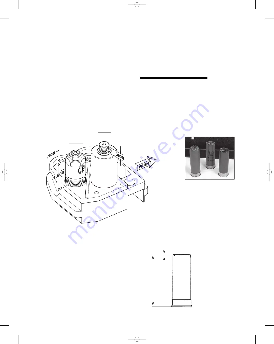
Here are some helpful adjustment settings for the SL 900 Shotshell Loader.  These settings

illustrate ideal adjustments for the starter crimp and the final crimp die. These settings can also

be used to reset these dies if you get completely out of adjustment.

Station 5, Final Crimp Die

Use dial calipers when measuring

these dimensions. See the bottom of

this page for additional adjustments.

Use dial calipers when measuring these

dimensions.

When you turn the starter crimp screw

clockwise (down), you are increasing the

amount of plastic that will be folded or

rolled closed.

When you turn the starter crimp screw

counterclockwise (up), you are decreasing

the amount of plastic that will be folded or

rolled closed.

Station 4, Starter Crimp Die

2.30 -

2.350

overall

length

seated depth

.065

Station 4

Starter Crimp

Screw

Final

Crimp

Die

Station 5

Seat Plug

Starter Crimp

Die Body

(non-adjustable)

Suggested Settings

49

SL 900, May 2007  5/21/07  11:51 AM  Page 49

Summary of Contents for SL 900

Page 1: ...illon recision Products Inc Manufacturers of The World s Finest Loading Equipment Dillon SL 900 Instruction Manual May 2007 SL 900 May 2007 5 21 07 11 51 AM Page 1 ...

Page 2: ...ep by Step Preliminary Assembly 17 21 Factory Settings 22 23 Filling the Machine with Components What s First 24 29 Changes and Adjustments 29 35 Adjusting the Collet Sizer 29 Powder Die Funnel Adjustments 30 Adjusting the Automatic Powder System Powder Charge Weight 30 Adjusting the Wad and Shot Station 30 Adjusting the Starter Crimp Die 31 Removing the Shot From the Machine 31 Removing the Toolh...

Page 3: ...16711 Primer Feedplate 16714 Slide Bellcrank Spring 16717 Primer Feed Cam 16721 Tray Mounting Bracket 16723 Primer Feed Body 16724 Shot Dispenser 16725 Shot Dispenser Body 16726 Shot Drop Tube 12 ga 16727 Shot Dispenser Bellcrank 16731 Spring Bellcrank Assembly 16732 Pivot Pin 16733 Shot Bar Return Rod 16735 Shot Body Collar 16737 Collar Guide Clamp 16738 Shot Bar 16739 Shot Bar Insert 16740 3 8 1...

Page 4: ...3988 4 Part Description 13856 1 4 Washer SAE 13911 1 4 20 x 2 3 4 Bolts 13988 1 4 20 Nuts 16065 650 Machine Mounts 16221 1 4 Fender Washer 16222 1 4 20 x 11 2 Hex Bolts 16672 Shotshell Chute 17125 Dillon Bin SL 900 Mounting Assembly SL 900 May 2007 5 21 07 11 51 AM Page 4 ...

Page 5: ...part Part Description 13418 Shellplate Bolt 13613 Clamp 13667 Index Pawl 13677 Ring Indexer 13791 Indexer Return Spring 13856 1 4 Washer SAE 13938 Pawl Spring 13966 1 4 28 x 3 4 SHCS 13988 1 4 20 Nuts 13989 10 24 x 5 8 SHCS 16675 Shellplate 12 ga 16676 Ejector Wire 16699 Spent Primer Cup 17123 SL 900 Casefeed Post 17124 Shot Post 17637 1 4 20 x 4 1 2 Hex Head Screw 5 SL 900 May 2007 5 21 07 11 51 ...

Page 6: ...724 17202 17139 17837 17479 17202 17139 17837 Part Description 16724 Shot Hopper 17139 Shot Dispenser Fitting 17202 Shot Fitting E Clip 17479 Clear Industrial Vinyl Tubing 17837 Tyton Clamp SL 900 May 2007 5 21 07 11 51 AM Page 6 ...

Page 7: ...w Zn 16314 Butt Connector 16336 Red 1 4 female Insulated Connector 16337 Blue 1 4 female Insulated Connector 17133 Shotshell Disc 17585 Zener Diode 1N5361B 17587 8x1 4 PHL PN Screws 17808 Casefeed Bowl Insert 97037 12 ga Casefeed Assembly 110v 97108 Shotshell Funnel Assembly 13779 Micro Switch 13954 4 40 Screws 14038 40 40 Nuts 16334 Lighted Rocker Switch 16704 Shotshell Funnel 17586 8x1 1 4 Funne...

Page 8: ...SL 900 Casefeed Post 17124 Shot Post 20536 SL 900 Casefeed Tube white label Part Description 13989 10 24 x 5 8 SHCS 14013 8 32x3 8 SHCS 14026 8 32 x 1 2 BHCS 16680 1 16 x 1 2 Roll Pin 16707 Phish Compression Spring 16708 Casefeed Phish 16709 Camming Pin 17130 Casefeed Sleeve 12 Ga 17131 Casefeed Body 17353 Phish Spring Socket 17472 8 Washer 032 Thick 8 SL 900 May 2007 5 21 07 11 51 AM Page 8 ...

Page 9: ...t 13700 Link Arm Shoulder Pin 13789 1 4 28 Set Screw 13830 Mainshaft Pivot Pin 13841 Nylock Nuts 13989 10 24 x 5 8 SHCS 14922 Link Arms 16670 SL 900 Crank 16671 Indexing Block 17182 SL 900 Frame 17637 1 4 20 x 4 1 2 Hex Head Screw 22183 Roller Handle Assembly 13704 Washer 2 13841 Nylock Nuts 17068 Handle Bar 17069 Clip 17918 Molded Handle 17182 9 SL 900 May 2007 5 21 07 11 51 AM Page 9 ...

Page 10: ... 1 4 Die Lock Ring 17149 1 0 Die Lock Ring 17351 Die Lock Bolt 17477 Collet Sizer Spring 17817 Powder Measure Assembly 17899 Stem Screw 17909 Eight Star Crimp 18140 Six Star Crimp 14008 Gauge Conversion Chart part description 12 Ga 20 Ga 28 Ga Crimp Die 11109 10604 10615 Seat Plug 11110 10611 10621 Collet Sizer 16743 10606 10618 Decap Pin 16741 10607 10613 Powder Funnel 16746 10608 10619 Star Crim...

Page 11: ...rt Slide Spring Cap 14689 8 32 x 1 4 BHCS 16209 Spent Primer Cup Bracket 16683 Case Insert Slide 16684 Slide Block 16691 Primer Transfer Arm 16692 Arm Pivot Pin 16693 Transfer Arm Spring 16694 Station Two Locator 16695 Locator Pivot Screw 16696 Locator Torsion Spring 16697 Case Insert Ramp 16699 Spent Primer Cup 16753 Locator Buttons 17126 Locator Button Spring 17472 8 Washer 032 Thick 17639 175 d...

Page 12: ... 1 4 28 Brass Tip Set Screw 14023 8 32 x 3 4 BHCS 14026 8 32 x 1 2 BHCS 14808 Collar Roller Bushing 16340 10 32 Nylock Nut 16714 Slide Bellcrank Spring 16717 Primer Feed Cam 16721 Tray Mounting Bracket Part Description 16723 Primer Feed Body 17132 Primer Drop Tube 17134 Primer Bellcrank 17354 Gate 3 17472 8 Washer 032 Thick 17474 10 32 x 5 8 Tray Cover Screw 17601 Washer 100 Thick 17603 Black Knob...

Page 13: ...52 Powder Bar Part Large 13853 Powder Bar Insert Large 13893 Powder Bar Post Large 13943 Powder Bar Bolt 13958 Powder Bar Bolt Washer 14041 Bowed Washer Return Rod Assembly 13799 Blue Wing Nut 13801 Tinnerman Nut 13848 Bellcrank Bushing 13858 Rod Compression Spring 13871 Bellcrank Cube 14041 Bowed Washer 16904 10 32x1 1 2 SHCS 17350 Powder Bar Return Rod 17838 P M Lock Link 17839 P M Slotted Bellc...

Page 14: ...ent Bolt 13958 1 4 Washer 13989 10 24 x 5 8 SHCS 13996 10 32 Set Screw 14013 8 32x3 8 SHCS 14023 8 32 x 3 4 BHCS 14026 8 32 x 1 2 BHCS 14041 1 4 Wave Washer 14808 Collar Roller Bushing 16725 Shot Dispenser Body 16726 Shot Drop Tube 12 ga Part Description 16727 Shot Dispenser Bellcrank 16733 Shot Bar Return Rod 16735 Shot Body Collar 16737 Collar Guide Clamp 16738 Shot Bar 16739 Shot Bar Insert 167...

Page 15: ...ses the depth the wad is seated into the shotshell Counterclockwise rotation lowers the shot dispenser tube and the wad will get seated deeper into the shotshell Finished Round Information Your loaded round length will vary due to loads used type of wads and brand of shotshells We found that a majority of the Winchester ammo loaded fell toward 2 30 2 325 length The Remington and Federal ammo loade...

Page 16: ...l This hull is no longer a one piece extruded design Now it is a two piece hull incorporating an inner reinforcing tube which extends partway up the interior of the hull Winchester wads have been redesigned to work with this new design Additionally some after market wads are now available which are compatible with the redesigned hulls Other wads may not be compatible with the new AA hulls We sugge...

Page 17: ...ll Raise the roller handle 22183 and push aft to prime Hold the handle aft while you insert a wad into the swing arm At station four we start the crimp in the top of the loaded hull It is formed and folded closed preparing the hull for the final crimp and seating performed in station five The formed folded top of the hull will now be crimped and seated closed This die is fully adjustable The crimp...

Page 18: ...ize yourself with its operation Notice how every time an empty hull exits the casefeeder it passes a microswitch Later in the loading process you will see that every time the hull is next to the microswitch the motor will shut off Fig 6 6 Place the casefeeder on its post Find the clear feed tube and place the bottom of the tube into the 12 Ga casefeed sleeve 17130 Align the casefeeder on the post ...

Page 19: ... clockwise will increase the powder charge weight Fig 9 Be sure to install the powder measure plug 13921 here see arrow Fig 9 8 Remove the blue cap on the powder die 16744 Loosen the two Allen screws and place the powder measure 17817 on the powder die 16744 The clamp must lock into the groove of the die then secure the two Allen screws firmly Fig 10 9 Locate the parts bag for your machine Enclose...

Page 20: ... rod 16733 clear shot feed tube two shot dispenser fittings 17139 two shot fitting e clips 17202 and two tube clamps Fig 13 12 Assemble the shot dispenser fittings to the clear shot feed tube Fig 14 Place the tube clamps loosely on the tube Slide one end of the shot dispenser fitting into the bottom of the shot hopper 16724 item A Fig 13 and lock it in using one of the shot fitting e clips Now ali...

Page 21: ...wer right hand side of the machine s platform slide the cup onto the bracket rails Fig 17 15 Position the Dillon bin 17125 on the machine s right side then place the shotshell chute 16672 between the machine and the Dillon bin 17125 Fig 18 16 Finally install the roller handle 22183 Fig 19 21 Fig 17 Fig 19 Fig 18 SL 900 May 2007 5 21 07 11 51 AM Page 21 ...

Page 22: ...s Fig 21A The powder die has been adjusted to a height so that the powder measure bellcrank can make full strokes when activated Fig 21B Turning the powder die 16744 counterclockwise will raise the powder system reducing the amount of stroke the bellcrank has Fig 21C Station Three Two operations occur here involving wad and shot insertion In the wad swing arm 16677 we ve installed a caliber specif...

Page 23: ... The starter crimp die 10640 forms and folds the loaded shotshell hull This die is set for Winchester AA hulls so we achieve 60 closure of the top Fig 24 Station Five Here we ll finish crimp and seat A final seat plug presses the hull back down and below the top by approximately 1 16 of an inch The taper crimp feature within the die radiuses and blends the end of the hull and locks the crimp on th...

Page 24: ...at steps 4 and 5 a minimum of four times so you are receiving a uniform powder charge 7 Weigh the fifth powder charge Using a 7 16 wrench rotate the bolt located on the end of the powder bar Counterclockwise will reduce the powder charge weight Clockwise will increase the powder charge weight Adjust as needed 8 Again repeat steps 4 and 5 until you re happy with the powder charge Now that you have ...

Page 25: ... the shot charge Remember to place the clear hopper lid 17138 back onto the shot dispenser tighten the bolt set screw 16740 Now that you have determined the shot charge let s move on to station four and five where the starter crimp die 10640 and final seat crimp functions are performed Let s use the same hull with shot 1 Place the hull with shot into station four 2 Move the roller handle 22183 dow...

Page 26: ...off automatically when a hull trips the microswitch Fig 39 Insure that the casefeed tube is fully seated into its clamp 5 Get one box of new shotshell primers 6 Slide the cardboard jacket back exposing only half of the first row of primers Fig 40 7 Turn the box of primers over 8 Place the leading edge of the primer tray into the machine s primer feedplate 16711 Fig 41 9 Slide the cardboard jacket ...

Page 27: ...sing the first hull as our guide 1 With all the stations empty move the roller handle 22183 down and then back up to its full aft position A hull has been fed into the shellplate Fig 45 2 Push the roller handle 22183 aft away from you Doing so inserts the hull fully into the shellplate and the first primer appears at station two Remove this primer and set it aside Fig 46 3 Move the roller handle 2...

Page 28: ...ller handle 22183 Fig 50 9 Move the roller handle 22183 down The first hull is at station three where a new plastic wad is seated It then receives a charge of shot Again the hulls in station one and station two are being processed as well Fig 51 10 Raise the roller handle 22183 to its full aft stop The first hull advances to station four and the other hulls advance as well Fig 52 If you encounter ...

Page 29: ... 16681 We ve now reached the stage in the reloading process where all the stations in the machine are filled From here on out every complete stroke of the roller handle 22183 will give you one completed round WHEN OPERATING THE ROLLER HANDLE Pay close attention to the hulls noting the changes that take place as they go through the machine Pace yourself when operating this machine Do not crash the ...

Page 30: ...t to go down too far or you may crush a hull Turning the powder die 16744 counterclockwise will raise the powder system reducing the amount of stroke the bellcrank has Fig 60 3 Adjusting the Automatic Powder System Powder Charge Weight Place a hull at station two and cycle the handle Weigh the powder charge from the hull and write that weight down Using a 7 16 wrench rotate the bolt located on the...

Page 31: ...640 down approximately one half turn clockwise as needed Reloading with Federal hulls and wads requires a little readjusting as well Raise the starter crimp die 10640 approximately one half turn counter clockwise This will help produce a uniform folded crimp seat Winchester hulls and Versatile wads loaded fine and required little or no adjustment at all Remington hulls and Versatile wads also load...

Page 32: ...es on a Dillon machine is the removable toolhead 16667 The removable toolhead 16667 allows you to convert from one hull brand to another hull brand or another caliber in a matter of minutes Let s use the following steps to remove and install a toolhead 16667 on the SL 900 machine 1 Empty all the shot from the shot hopper 16724 and clear tube via the shot drain 2 Remove the shot fitting e clip and ...

Page 33: ... 22183 halfway down its stroke 3 Use a 1 8 Allen wrench to loosen the 1 4 28 brass tip set screw 13923 located on the left side of the machine below the platform in the mainshaft 13485 Fig 72 4 Return the roller handle 22183 to its rest position 5 Use a 1 4 Allen wrench to unscrew the shellplate bolt 13418 6 Remove the shellplate from the machine Fig 73 Be careful not to lose the 3 8 index ball 13...

Page 34: ... Pour the powder out of the hopper back into its original container 5 Turn the powder system upright and position the unit over the opening of the powder container and cycle the powder bar with your thumb Fig 79 6 Once the powder system is completely empty reinstall the powder system and tighten the two 10 24 screws using a 5 32 Allen wrench 7 Reattach the powder bar return rod 17350 8 Refill the ...

Page 35: ...rease on the primer feed plate This hinders the free flowing operation of the system 2 Never allow excess powder or dirt to build up on the deck where the primer transfer arm 16691 swings in and out of the machine If you decide to service your machine or don t wish to have any primers feeding install the stop block into the primer system as shown When you re ready to resume simply remove the stop ...

Page 36: ... 900 reloading manual as needed 1 Drain the shot via the shot dispenser drain Hint use an old coffee can widemouth water jug or shot bag to catch the shot 2 Disconnect the return rods on both the shot and powder dispensers 3 Remove the shot fitting e clip on the shot dispenser and slide the fitting out of the dispenser housing 4 Remove the two black toolhead pins and remove the toolhead from the m...

Page 37: ...e it in the platform press down and rotate as needed to allow the locator button to snap into place Fig 4a 9 At Station 2 place the green locator insert 28 gauge onto the Station 2 locator Fig 5 10 Move the roller handle to the down position 11 Place the 28 gauge shellplate on the platform Fig 6 12 Insert the shellplate bolt Use a 1 4 Allen wrench to thread the shellplate bolt down until it stops ...

Page 38: ...asefeed body Fig 8 3 From the 28 gauge conversion box retrieve the 28 gauge casefeed sleeve and place it on the casefeed body Reinstall the screw and washer onto the casefeed sleeve assembly Note the difference in diameter between the two pieces Fig 9 4 Remove the 12 gauge disc from the casefeed bowl Fig 10 Both 20 and 28 gauge hulls use the small gauge disc Fig 11 Fig 11 Fig 10 Fig 9 Fig 8 Fig 7 ...

Page 39: ...clamp screws using a 5 32 Allen wrench 3 Install both return rods onto the shot dispenser and the powder measure 4 Realign the shot hopper tube fitting with the shot dispenser Insert the fitting and the e clip into the dispenser top 5 Cycle the roller handle two complete cycles to insure everything is free to move 6 Fill the shot dispenser with one cup of shot 7 Remove the lid on the powder measur...

Page 40: ...and 5 the starter crimp die and final seat crimp functions are performed 19 Using the same hull with shot in it in Station 4 move the roller handle down and then back to its rest position the formed and folded hull has just completed Station 4 and has advanced to Station 5 Fig 17 20 Once again move the roller handle down As you return the roller handle to its rest position you ll see the completed...

Page 41: ... 900 reloading manual as needed 1 Drain the shot via the shot dispenser drain Hint use an old coffee can widemouth water jug or shot bag to catch the shot 2 Disconnect the return rods on both the shot and powder dispensers 3 Remove the shot fitting e clip on the shot dispenser and slide the fitting out of the dispenser housing 4 Remove the two black toolhead pins and remove the toolhead from the m...

Page 42: ...rm and rotate the locator button until it snaps free Fig 4 Remove all three locator buttons Next retrieve the new locator buttons from the 20 gauge conversion box Place the spring on the locator button place it in the platform press down and rotate as needed to allow the locator button to snap into place Fig 4a 9 At Station 2 place the yellow locator insert 20 gauge onto the Station 2 locator Fig ...

Page 43: ...gauge casefeed sleeve off the casefeed body Fig 8 3 From the 20 gauge conversion box retrieve the 20 gauge casefeed sleeve Fig 9 and place it on the casefeed body Reinstall the screw and washer onto the casefeed sleeve assembly 4 Remove the 12 gauge disc from the casefeed bowl Fig 10 Both 20 and 28 gauge hulls will use the small gauge disc Fig 11 5 Install the small gauge disc into the casefeed bo...

Page 44: ...h your powder of choice 8 Use a once fired hull place the hull in Station 2 where the powder measure is located Fig 14 9 Move the roller handle down and then back up to its rest position Remove the hull from the shellplate by pressing down on the locator button Fig 15 Pour the powder back into the clear powder hopper 10 Repeat these two steps a minimum of four times to make sure you are receiving ...

Page 45: ...ed hull has just completed Station 4 and has advanced to Station 5 Fig 17 20 Once again move the roller handle down As you return the roller handle to its rest position you ll see the completed round advance and move out of the machine 21 Inspect the completed round 22 Before you begin reloading review all assemblies to assure yourself that all the screws you touched are tight You are now ready to...

Page 46: ... feed well in any machine when they re greasy 6 How do I stop the primers from feeding A rectangular insert has been included with the machine Place your thumb on the primer drop tube and raise the primer system by pushing it up Insert the stop block BETWEEN the primer feed body and the tray mounting bracket Remove the stop block when you re ready to begin reloading again 7 When I operate the mach...

Page 47: ...en using the SL 900 It may be that the first shotshell has struck the mouth of the sizing die or a wad or smaller gauge shotshell is stuck inside the first shotshell and has jammed itself onto the depriming pin Or it may be that a wad has not entered the shotshell properly and is caught on the mouth of the shotshell Whatever the cause remove the suspect round by lowering the shotshells out of the ...

Page 48: ...te Bolt Hole E Case Insert Slide Arm Ramp F Wad Sleeve G Wad Swing Arm Pivot Hole H Powder Body Collar rails hole and roller bellcrank I Lock Link 16730 J Around the Collet Sizer Sleeve 16742 K On the Ring Indexer and Indexer Block L A very light amount on the surface of the Primer Drop Tube M Primer Feed Body Rails N The Main Pivot Hole in all Bellcranks O Primer Feed Cam 16717 Cam Slot P 1 4 Dia...

Page 49: ...some helpful adjustment settings for the SL 900 Shotshell Loader These settings illustrate ideal adjustments for the starter crimp and the final crimp die These settings can also be used to reset these dies if you get completely out of adjustment Station 5 Final Crimp Die Use dial calipers when measuring these dimensions See the bottom of this page for additional adjustments Use dial calipers when...

Page 50: ...r The SL 900 is pictured with optional accessories Low Powder Sensor 16306 Aluminum Roller Handle 17950 Other accessories available for the SL 900 include 12 gauge conversion 22009 20 gauge conversion 22138 28 gauge conversion 22139 20 28 casefeed plate 97045 Machine Cover 13329 The Blue Press Dillon s monthly catalog has a complete listing of accessories available for all machines 50 SL 900 May 2...

Reviews: