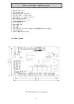
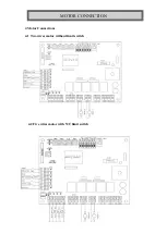
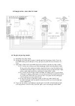
DIGIWAY PTY SW50-2 Instruction Manual Download Page 11


- 11 - 


Control Terminals


OPN ----- N/O open input.  
PED ------ N/O pedestrian open push button, only open motor-1 
PEB ------ N/C photo electrical beams 
OSC------ N/O Open – Stop – Close--Open 
OL1 ------ Motor 1 open limit switch, N/C or N/O selected by DIP4  
CL1 ------ Motor 1 close limit switch, N/C or N/O selected by DIP4 
OL2 ------ Motor 2 open limit switch, N/C or N/O selected by DIP4 
CL2 ------ Motor 2 close limit switch, N/C or N/O selected by DIP4 
 
Buttons 
OPN button ---- Full (M1&M2) open gate and used for settings 
PED button ----- Ped (M1) open gate and used for settings 
CLS button ----- CLS gate and used for settings 
OSC button ----- Open – Stop – Close—Open and for setting 
 

3.2 DIP Switch Settings 

DIP1---- SET  

ON—set,  


OFF – Run 

DIP2---- SYNC 

ON—SYNC mode,   


OFF – No Sync mode 

DIP3---- DIP3 

Spare for V4.2 and before 

DIP4---- CODE 

ON—Encoder control M1 only,   OFF – limit control 

DIP5---- LKPS 

ON—Lock Pulse Output,    

OFF – Lock Presence Output 

DIP6---- NOLS 

ON—N/O limit switch,  


OFF – N/C limit switch 

DIP7---- PECL 

ON—PE trig Auto Close,    

OFF – No PE trig Auto close 

DIP8---- AUCL 

ON—Auto Close Mode,    

OFF – No Auto close 

 
3.3 Motor Force 

If any motor current over current setting, both motors will stop in opening cycle or reopen in 
closing.  
If gate(motor) already in low-speed section and nearly closed or opened, controller will not 
response the overload  
 

3.4 Power input 

12 or 24V AC power input. 12VAC for 12VDC motor, 24VAC for 24V DC motor 
 

3.5 Battery Backup 

12V battery --- 12VDC motor, 12VAC input. 
24V battery --- 24VDC motor, 24VAC input. 

Solar regulator output can be direct connected to this terminal if in case of solar application. 


3.6 Motor output 

M1: Motor 1 output. M2: Motor 2 output 
 

3.7 Power output 

Power out for accessaries. About 14V----- 12VAC supply, about 26V------24VAC supply 

 
3.8 Timers setting  

Push Buttons functions 
Button 

SET 

ON---Setting 

SET OFF

---Running  

Note 

OPN 

Sync Delay Time 

Open gate 


PED  

Lock Pulse Time 

Lock pulse Time 


CLS 

PE Trig Close Time 

PE Trig Close Time 


STP 

Auto Close Time 

Auto Close Time 


CONTROLLER SETTINGS 

Summary of Contents for SW50-2

Page 1: ...1 SW50 2 Dual Swing Gate Motor INSTRUCTION MANUAL DIGIWAY PTY LTD...

Page 2: ...s to prevent personnel from being injured by motorized device being controlled All main voltage wiring must be installed by a licensed electrician Recommended install PE beams or loop detectors for ad...

Page 3: ...The arm supplied can be met most of application situations If special need customer can modify arm or ask supplier dealer to contact manufacturer for different arm Before installation must check A Gat...

Page 4: ...4 Standard installation for brick post Gate Swing in GATE MOTOR MOUNTING Opened position Opened position Closed Position Closed Position...

Page 5: ...5 Gate swing in Brick Post Gate Swing Out Opened position Opened position Closed Position Closed Position...

Page 6: ...6 Steel Post swing out application Steel Post small side room swing in with special parts Opened position Closed Position Closed Position Opened position...

Page 7: ...7 Special limited side room cut the arm to suit the application Closed Position Opened position...

Page 8: ...handle 2 push handle to the position 3 Push motor up and left direction NOW GATE IS FREE TO MOVE 4 Push motor down and right direction Make sure gears engaged 5 push manual release handle clockwise a...

Page 9: ...For Swing gates Sliding Gates Roller shutter doors etc Limit switch inputs N C or N O Lock or lights relay output Adjustable timers auto close time and PE trig auto close time Pedestrian cycle Safety...

Page 10: ...d 6 Mode selection DIP switch 7 Close motor force reverse power 8 Control inputs terminals 9 Limit switch input 10 Lock output relay 11 M1 output 12 M2 output 13 Accessories power 14VDC or 26VDC depen...

Page 11: ...N O limit switch OFF N C limit switch DIP7 PECL ON PE trig Auto Close OFF No PE trig Auto close DIP8 AUCL ON Auto Close Mode OFF No Auto close 3 3 Motor Force If any motor current over current settin...

Page 12: ...d CLS button then power on While hold CLS button set SET1 off and then release the CLS button Now controller restored factory setting from memory Special settings To get into Special Setting Turn powe...

Page 13: ...13 4 Motor Connections 4 1 Two wires motor without limit switch 4 2 Five wires motor with N C limit switch MOTOR CONNECTION...

Page 14: ...nect to closed limit switch in put on control board Open gate to opened position do the same things for opened limit switch 2 If 2 wires system with limit switch with diode need keep power on push rem...

Page 15: ...te not open 1 Check the limits switch type selection if it is right 2 Push button on the control board if gate status green LED flashing and red LED off please check motor fuse and motor 5 3 Gate not...

Reviews: