background image

9

DIODE TEST

The value that displays on screen during the diode check is the forward voltage. 

1)  Set the function switch to the Ω 

  CAP position.

2)  Insert the black test lead banana plug into the negative COM jack.

3) Insert the red test lead banana plug into the positive VΩCAP jack.

4)  Press the MODE button until display on the screen.

5)  Touch the test probes to the diode or semiconductor being tested.

6)  Reverse the probe polarity by switching probe position. Note this reading. 

7)  The diode or junction can be evaluated as follows:

  A)  If one reading shows a value and the other reading shows OL, the diode is 

good.

  B)  If both readings show OL, the device is open.

  C)  If both readings are very small or zero, the device is shorted.

CAPACITANCE MEASUREMENTS

To avoid electric shock, disconnect power to the area being tested and discharge 

all capacitors before taking any capacitance measurements.

1)  Set the function switch to the Ω 

 CAP position.

2)  Insert the black test lead banana plug into the negative COM jack.

3) Insert the red test lead banana plug into the positive VΩCAP jack.

4)   Press the MODE button until “nF” displays on the screen.

5)  Touch the test leads to the capacitor being tested. 

6)  The test may take up to three minutes or more for large capacitors to charge. 

Wait until the readings settle before ending the test.

7)  Read the capacitance value displayed on the screen.

TEMPERATURE MEASUREMENTS

The temperature probe is fitted with a type K mini connector. A mini connector to 

banana connector adaptor is supplied for connection to the input banana jacks.

1)  Set the function switch to the temp position.

2)  Insert the temperature probe into the input jacks, making sure to observe the 

correct polarity.

3)  Press the MODE button to indicate “ºF” or “ºC”.

4)  Touch the temperature probe head to the part you wish to measure. Ensure 

the probe remains in contact with the part until the reading stabilises (about 

30 seconds).

5)  Read the temperature displayed on the screen.

Summary of Contents for QM-1500

Page 1: ...HOBBYIST Low Cost Digital Multimeter QM1500...

Page 2: ...e the test leads before replacing the battery or fuses Before using the meter please inspect the condition of the test leads and the meter itself for any damage If damage is present please discontinue...

Page 3: ...Display 2000 counts Basic Accuracy 0 500 DC Voltage Range 400mV 1000V AC Voltage Range 4V 1000V DC Current Range 4mA 10A AC Current Range 4mA 10A Resistance 400 40M Capacitance CAP 4nF 100 F Frequency...

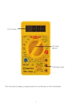
Page 4: ...4 The tilt stand battery compartment are at the rear of the multimeter LCD Screen Function Switch COM Input Jack...

Page 5: ...ion with the function switch to measure things like resistance diode continuity and capacitance It also allows you to select between AC or DC current measurements Function Switch Select a measurement...

Page 6: ...ESCRIPTION Continuity Diode Test Low Battery F Farads Capacitance Ohms Hz Hertz Frequency V Volts A mA A Current Range AC Alternating Current Voltage AUTO Autoranging DC Direct Current Voltage HOLD Di...

Page 7: ...000 A DC set the function switch to the A position and insert the red test lead banana plug into the A jack For current measurements up to 400mA DC set the function switch to the mA position and inser...

Page 8: ...batteries and unplug the line cords 1 Set the function switch to the CAP position 2 Insert the black test lead banana plug into the negative COM jack 3 Insert the red test lead banana plug into the p...

Page 9: ...urements 1 Set the function switch to the CAP position 2 Insert the black test lead banana plug into the negative COM jack 3 Insert the red test lead banana plug into the positive V CAP jack 4 Press t...

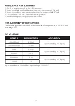
Page 10: ...obes to the circuit being tested 5 Read the frequency displayed on the screen MEASUREMENT SPECIFICATIONS The following guide is based on an environmental temperature of 18 28 C and humidity 70 RANGE R...

Page 11: ...ut voltage 1000VAC RMS Frequency range 50 400Hz all AC voltage ranges are specified from 5 of range to 100 of range DC CURRENT RANGE RESOLUTION ACCURACY 400 A 0 1 A 1 2 reading 3 digits 4000 A 1 A 40m...

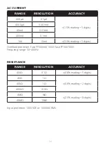
Page 12: ...0A 10mA 3 0 reading 5 digits AC CURRENT Overload protection fuse FF500mA 1000V fuse FF10A 500V Frequency range 50 400Hz RESISTANCE Input protection 1000VDC or 1000VAC RMS RANGE RESOLUTION ACCURACY 400...

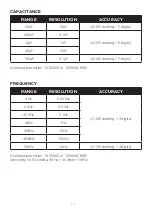
Page 13: ...MHz 1kHz 1 2 reading 4 digits FREQUENCY Overload protection 1000VDC or 1000VAC RMS Sensitivity 0 5V while 1MHz 3V while 1MHz RANGE RESOLUTION ACCURACY 40nF 10pF 5 0 reading 7 digits 400nF 0 1nF 3 0 re...

Page 14: ...he rear battery cover with a screwdriver 3 Remove the old battery and insert the new battery into the battery holder observing the correct polarity 4 Put the battery cover back in place secure with th...

Page 15: ...0 5 AC Voltage 200V 750V max input 750V RMS 1 2 DC Current 200 A 2mA 20mA 200mA 10A 1 2 Resistance 200 2k 20k 200k 2M 1 2 Measurement Type Average Input Impedence 1 Dimensions 125 H x 68 W x 23 H mm W...

Page 16: ...16 Distributed by TechBrands by Electus Distribution Pty Ltd 320 Victoria Rd Rydalmere NSW 2116 Australia Ph 1300 738 555 Int l 61 2 8832 3200 Fax 1300 738 500 www techbrands com...

Reviews: