DIGITAL YACHT LTD
AIT1000 Quick Start Guide
1. Introduction
Congratulations on the purchase of your AIT1000 Class B AIS Transponder. It is recommended that your transponder is
installed by a professional installer.
Before operating the unit you should familiarise yourself with the complete user manual supplied with the
product.
2. Before you start
You will need the following items and tools to complete the installation:
Class B AIS Transponder.
Dedicated VHF/AIS antenna and cable
– not supplied
Dedicated GPS antenna and cable - supplied
Access to 12V DC power supply where the unit is to be installed.
Four M4 screws or other fixings appropriate to the mounting location.
Transponder power and data cable - supplied
To configure the unit you will need:
Access to a PC running Microsoft Windows XP
®
/ Windows Vista
®
/ Windows 7 with a free USB port.
proAIS Class B AIS Transponder configuration software.
An MMSI number for your vessel
Note:
You can obtain an MMSI (Maritime Mobile Service Identity) from the same authority that issues ship radio
licences in your area. An MMSI may have already been provided with your existing VHF radio licence. The MMSI
number used for the AIS Transponder should be the
same
as that programmed into your VHF DSC radio.
If you do not have an MMSI number the AIS Transponder will operate in receive only mode.
Do not enter an invalid MMSI number.
3. Installation
Before starting installation select a suitable location for the AIS Class B Transponder. The unit is water resistant; however
it should be installed below deck in a dry location. When locating the unit you should consider:
Routing of power and antenna cables to the unit.
Provision of sufficient space behind the unit for cable connections.
Routing of data connections to PC or chart plotter from the unit.
Maintaining the compass safe distance of 0.5m.
Visibility of the front panel indicators.
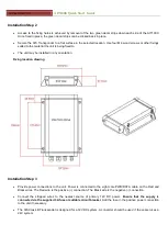
Installation Step 1
Install VHF and GPS antenna according to the hand book instructions and following guidance and warnings in the
main user manual for the AIS Class B Transponder.
Run VHF and GPS antenna co-axial cables to the AIS Class B Transponder and terminate with the correct
connectors:
The VHF antenna cable should be terminated in a BNC connector
The GPS antenna cable should be terminated in a TNC connector


