

DWC-MTT4WiA
Mounting
template
Rubber
plug
Default Login Information
Username: admin
Password: admin
Quick Start Guide
Quick Start Guide
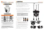
WHAT’S IN THE BOX
Quick setup
guide
1
Tapping
screws PA
4x35 – 3pcs
1 set
Mounting
template
1
Plastic plugs
– 3pcs
1 set
Waterproof
cap
1
Allen
wrench
1
Rubber plug
1
1. The mounting surface must bear three times the weight of your camera.
2. Do not let the cables get caught in improper places or the electric line cover to
be damaged. This may cause a breakdown or fire.
3. Using the mounting template sheet or the camera itself, mark and drill the
necessary holes in the wall or ceiling.
1. To use the camera’s waterproof wiring:
a. Install the LAN cable into .
b. will be assembled to
with a 1/4 turn.
c. Thread tightly to .
2. Adjust the camera to obtain an optimum angle by loosening the lock
screw, located under the camera’s lens module. Tighten the lock
screws after you finish adjusting the view angle of the camera.
3. Adjust the focus and zoom screws at the base of the camera module
to achieve a clear image.
4. Remove the protection film softly to complete the installation.
Pass the wires through the mount bracket and make all necessary connections.
a. NETWORK CONNECTIONS – If you are using a PoE Switch, connect the
camera using an Ethernet cable for both data and power.
b. NETWORK CONNECTIONS – If you are using a non-PoE switch, connect the
camera to the switch using an Ethernet cable for data transmission and use a
power adapter to power the camera.
STEP 1 – PREPARING TO MOUNT THE CAMERA
STEP 3 – INSTALLING THE CAMERA
STEP 2 – CABLING THE CAMERA TO EXTERNAL DEVICES
a
a
b
b
c
NOTE:
To ensure moisture seal, make sure the o-ring is in place
between and . In extreme environments use of an
outdoor rated sealer is recommended.
a
b
NOTE:
When using the waterproof cap, crimp the RJ45 connector
after passing the cable through the waterproof cap.
Power Requirements
Power Consumption
DC 12V
POE IEEE 802.3af
Max. 5.5W
NOTE:
Download all your support materials and tools in one place
1. Go to: http://www.digital-watchdog.com/support-download/
2. Search your product by entering the part number in the ‘Search by Product’
search bar. Results for applicable part numbers will populate automatically
based on the part number you enter.
3. Click ‘Search’. All supported materials, including manuals, Quick Start
Guides (QSG), software and firmware will appear in the results.
Tel: +1 (866) 446-3595 / (813) 888-9555
Technical Support Hours:
9:00AM – 8:00PM EST, Monday through Friday
digital-watchdog.com
Attention: This document is intended to serve as a quick reference for the
initial setup. It is recommended that the user read the entire instruction
manual for complete and proper installation and usage.
Fo
cu
s
Zoo
m
Fo
cu
s
Zoo
m
Lock
screw