background image

Check Points Before Operation

1. Before you can start controlling your PTZ37X camera, you need to make sure the Camera’s ID,

    Baud Rate and Protocol are setup in the DVR or Joystick Controller. 

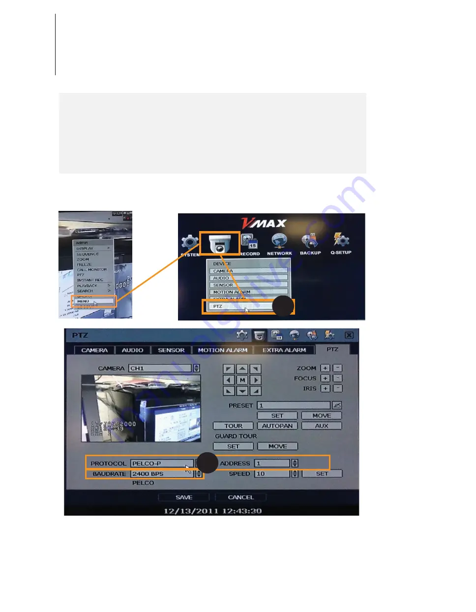
2. In the DVR, go to Menu --> Device --> PTZ

3. Setup the Protocol, Baud Rate and Address to match the information collected from the

    Initializing System page. 

    Note: If you do not have the information from the Initializing System screen, go to the PTZ37X’s 

    OSD menu, System Information. Please see page ____ for further information on how to navigate

    in the OSD menu using a DVR’s mouse.

4. Since the operation method can be different for each controller available, refer to the manual for

     your controller if camera can not be controlled properly

2

3

21

Summary of Contents for DWC-PTZ37X

Page 1: ...DWC PTZ37X DWC PTZ37XAL DWC PTZ37XFM Analog PTZ Outdoor Before installing and using the camera please read this manual carefully Be sure to keep it handy for future reference User sManual x37...

Page 2: ...the power cord into the power receptacle Insecure connection may cause fire 5 When installing the camera fasten it securely and firmly A falling camera may cause personal injury 6 Do not place conduct...

Page 3: ...or reinstall it 4 Remove the power plug from the outlet when there is a lightning Neglecting to do so may cause fire or damage to the product 5 Keep out of direct sunlight and heat radiation sources...

Page 4: ...onsult an electrician for replacement of the obsolete outlet 10 Protect the power cord from being walked on or pinched particularly at plugs convenience receptacles and the point where they exit from...

Page 5: ...Rules of Key Operation for Menu OSD ROOT MENU SYSTEM INFORMATION OSD DISPLAY SETUP CAMERA ID OSD DISPLAY SETUP PRIVACY ZONE OSD MOTION SETUP OSD FUNCTION SETUP PRESET SETUP OSD FUNCTION SETUP SCAN SE...

Page 6: ...can A group is composed of maximum 20 entities of preset pattern or scan Maximum 8 privacy zones can be set up to protect privacy of other people 7 rules of schedule can be assigned by day and time Ap...

Page 7: ...e Control 3 At Least Two 2 Terminal Boxes Matching the camera s RS 485 Terminal and your Joystick Controller DVR Alarm Sensor and Audio In and Out 4 Drill 5 Screw Driver 1 PTZ Mechanism 2 Sunshield Up...

Page 8: ...on what are dip switches and how to set them up The inner box also includes the camera s power supply outlet and video communication and alarm input output Sunshield Upper Housing The Sunshield protec...

Page 9: ...ver this will not recognize the AD protocol If you want to control the camera using the DVR or system keyboard the protocol set in the camera s inner box must be identical to the camera protocol setup...

Page 10: ...r By default the RS 485 Termination Resistor is OFF When you have a long daisy chain style connection turn ON this termination switch for the camera furthest from the controller ON 8J 2 1 3 4 5 6 7 8...

Page 11: ...x matching the camera s Inner box RS 485 Terminals Connect the other end of the cable to a terminal box matching the DVR or keyboard controller RS 485 Terminals 2 Make sure not to flip negative and po...

Page 12: ...e current capacity of the rated power carefully Rate Power Current Consumption Input Voltage Range AC 24V 2 5A AC 19V 29V Power 2 1 Connect AC power adapter to the camera s inner box 2 Make sure to co...

Page 13: ...Video Output 1 Connect BNC coaxial cable to camera s inner box 2 Connect the other end of the BNC Coaxial cable to a DVR or Monitor Video Output BNC Video Cabling 1 2 13...

Page 14: ...mal Open and Normal Close If sensor type is not selected properly the alarm can be activated reversely Alarm Output The 4 alarm outputs are the relay contact type Therefore you do not have to worry ab...

Page 15: ...e four 4 bolts Note the Anchor bolts included in with the camera kit are for concrete Be sure to consult with your installer what bolts are necessary depending on the wall ceiling surface 4 Using a dr...

Page 16: ...old both black handles on the camera mechanism Pull them up to detach the camera 6 Pass the cable connector from the inner box through the upper housing pipe 7 If inner box is located in the upper hou...

Page 17: ...wire to the safety hook on the upper housing and using the safety hanger secure it to the mounting box bracket 10 Screw in the upper housing to the Mounting box bracket Turn the upper housing at leas...

Page 18: ...orrespond with the A and B markings on the sides of the upper housing Note Before snapping the camera back into the housing make sure the cables are properly secured 13 Remove protecting gear from the...

Page 19: ...y 15 Camera will show Initializing Setup screen Note Please record the information on this screen especially the Protocol If set to Auto it is probably Pelco D Baud Rate and Camera s Address 16 When i...

Page 20: ...ing place the dome cover on the upper housing 18 Secure dome to camera by fastening the screws on the dome in the order shown below Note This order of fastening the screws guarantees optimal sealing a...

Page 21: ...dress to match the information collected from the Initializing System page Note If you do not have the information from the Initializing System screen go to the PTZ37X s OSD menu System Information Pl...

Page 22: ...set key 171 Sets camera BLC mode to HIGH Preset key 174 Sets camera focus mode to AUTO Preset key 175 Sets camera focus mode to MANUAL Preset key 176 Sets camera focus mode to SEMI AUTO Preset key 177...

Page 23: ...arm input function can be configured for each application How to Move Around the OSD Menu 1 Select Full Screen view on the selected PTZ camera 2 Right Click the screen Select PTZ 3 Right Click the scr...

Page 24: ...from one edit tab to the one to its left RIGHT Vertically move from one edit tab to the one to its right 6 Using the mouse s wheel move Forward to save changes and enter from the Root menu to a sub m...

Page 25: ...to enter scroll the mouse s wheel forward To exit a sub menu 3 When you have completed all desired modifications scroll the mouse s wheel backwards to return to the Root menu How to Move Around the O...

Page 26: ...vious instructions select the sub menu and category you wish to modify 2 Scroll the mouse s wheel forward to enter edit mode 3 The system will show it is in edit mode by highlighting the first tab How...

Page 27: ...the first data tab click on the left side of the screen to move to the next data tab 6 The system will show it is in edit mode by highlighting the second tab Repeat as necessary 7 When editing is comp...

Page 28: ...created by a joystick controller and revives the path exactly as it memorized for an assigned time See section ROOT MENU FUNCTION SETUP PATTERN SETUP 3 1 Set Pattern To set pattern use OSD menu 2 Run...

Page 29: ...OVER Store preset 123 It reached preset 123 The camera is running pattern 9 The camera is running scan 1 The action received is not within the range supported UNDEFINED The action received is not defi...

Page 30: ...ON TITLE PRESET LABEL ALARM I O DATE TIME PRIVACY ZONE BACK EXIT ON AUTO AUTO AUTO AUTO ON DISPLAY SETUP CAMERA ID PTZ INFORMATION ACTION TITLE PRESET LABEL ALARM I O DATE TIME PRIVACY ZONE BACK EXIT...

Page 31: ...RAMTION Shows information and current system configuration DISPLAY SETUP Enable Disable OSD display on main screen MOTION SETUP Configures motion related settings FUNCTION SETUP Configures various fun...

Page 32: ...k l mn o p q r s t u v w x y z CAMERA ID OK CANCEL CAMERA ID OK CANCEL 1 2 3 4 5 6 7 8 9 0 A B C D E F G H I J K LMN O P Q R ST U VWX Y Z a b c d e f g h i j k l mn o p q r s t u v w x y z 1 2 3 4 5 6...

Page 33: ...Sets the style of the mask See the next page MoveCameratoAreatoMask Press Near Enter Key PRIVACY ZONE MASK NO EDIT MASK BACK EXIT 1 UNDEFINED EDIT MASK 1 MOVE TO TARGET POSITION ENTER SELECT 0 0 x1 E...

Page 34: ...JUST Press Near Enter Key Press Near Enter Key Press Near Enter Key 7 PRIVACY ZONE MASK NO EDIT MASK DISPLAY CLEAR STYLE BACK EXIT 1 ON CANCEL COLOR PRIVACY ZONE MASK NO EDIT MASK DISPLAY CLEAR STYLE...

Page 35: ...ay the captured image during the present movement and will not display the images the camera receives during the movement As soon as the camera stops at the preset end point the camera begins to displ...

Page 36: ...N O ALARM 2 N O ALARM 3 N O ALARM 4 N O ALARM 5 N O ALARM 6 N O ALARM 7 N O ALARM 8 N O BACK EXIT ALARM INPUT SETUP ALARM 1 N O ALARM 2 N O ALARM 3 N O ALARM 4 N O ALARM 5 N O ALARM 6 N O ALARM 7 N O...

Page 37: ...can be set independently or separately for each preset in each preset setup menu Each special WB AE value should be activated correspondingly when camera arrives at each preset location During jog op...

Page 38: ...aracter from the character set To choose the character press the Near or Enter key Space If you want to use blank choose the space character Backspace If you want to delete a character in front use ba...

Page 39: ...camera turns on its axis by 360 in CW direction and then it turns on its axis by 360 in CCW direction SCAN NO Selects the scan number to edit If a selected scan has not defined NOT USED is displayed...

Page 40: ...e pattern recording press Near or Enter key 3 To exit this menu press Far key EDIT PATTERN Recording 1 Move the camera with joystick controller or run preset function to memorize the path mostly curve...

Page 41: ...umber CLEAR GROUP Deletes the data in the current group EDIT GROUP Starts editing group 1 8 CANCEL OK ACTION NO DWELL TIME Sets dwell time between function by moving joystick up down OPT Represents pr...

Page 42: ...NO DWELL OPT 1 PATTERN 1 00 03 1 2 NONE 3 NONE 4 NONE 5 NONE SAVE CANCEL Press Near Enter Key Press Far Key EDIT GROUP Selects Function Sequence When you finish setting up an ACTION press Near or Ent...

Page 43: ...ery day WKD Applies to every day except for Saturday and Sunday SUN MON Applies to designated day only TIME Set the time ACT NO Set the function and no ON Decide to make this rule effective or not ON...

Page 44: ...3 THU 11 40 SCN 3 ON 4 ALL 12 00 SCN 1 ON 5 UNDEFINED 6 UNDEFINED 7 UNDEFINED BACK If the rules conflict with each other the higher number will have priority over the others If you assign undefined f...

Page 45: ...DJUST BLUE ADJUST BACK EXIT DAY ATW2 0 0 Press Near Enter Key 2 WB SETUP NIGHT 6 BRIGHTNESS When NIGHT is selected it sets the criterion of the automatic day night selection If set to LOW the image ha...

Page 46: ...ct can be photographed without the ghost effect However the images can be dark if the scene lacks sufficient lighting If SENS UP is set to AUTO SHUTTER SPD is deactivated SENS UP Activates the slow sh...

Page 47: ...o Color with BRIGHTNESS set as HIGH the image will appear brighter DWELL TIME When the switching criterions are satisfied the filter is changed after the status is maintained during the dwell time MAS...

Page 48: ...ed by AGC can be reduced If set to HIGH the color range of the noise will decrease but the overall quality of the color will also decrease PIP Turn ON to display the sub screen Sub screen will appear...

Page 49: ...e is displayed in HH MM SS format ENGLISH ESPA OL FRAN AIS DEUTSCH ITALIANO PORTUGU S 01 JAN 2000 31 DEC 2037 RELAY1 2 3 4 Define the type of relay output for each of the four relays NORMAL OPEN NORMA...

Page 50: ...Southeast SW Southwest SET HOME POSOTION MOVE TO TARGET POSITION NEAR SELECT FAR CANCEL 0 0 x1 E SET NORTH DIRECTION MOVE TO TARGET POSITION NEAR SELECT FAR CANCEL 0 0 x1 N SET HOME POSITION Home posi...

Page 51: ...N OFF AUTO AUTO AUTO AUTO ON Undefined Address Camera ID PTZ Information Action Title Preset Label Alarm I O Date Time Privacy Zone OFF ON ON 140 sec NORMAL OFF OFF OFF Preset Lock Power Up Action Aut...

Page 52: ...Specifications Dimension Unit mm 170 101 5 260 52 38 1 1 5...

Page 53: ...co D Pelco P Samsung Panasonic Kalatel AD American Dynamics Selectable 12 Zones Built in 8 Input 4 Relay Output Menu PTZ Information etc Support 7 Languages ENGLISH ESPA OL FRAN AIS DEUTSCH ITALIANO P...

Page 54: ...er the CAMERA SETUP AE SETUP menu is OFF Color is not correct Check the setting of CAMERA SETUP WB SETUP menu The screen flickers continually Check that the camera is not pointing at the sun When RS48...

Page 55: ...adjustments improper antenna inadequate signal pickup maladjustment of consumer controls improper operation power line surge improper voltage supply lightning damage rental use of the product or servi...

Page 56: ...F ON OFF OFF OFF 23 ON ON ON OFF ON OFF OFF OFF 24 OFF OFF OFF ON ON OFF OFF OFF 25 ON OFF OFF ON ON OFF OFF OFF 26 OFF ON OFF ON ON OFF OFF OFF 27 ON ON OFF ON ON OFF OFF OFF 28 OFF OFF ON ON ON OFF...

Page 57: ...F ON OFF ON ON ON OFF OFF 59 ON ON OFF ON ON ON OFF OFF 60 OFF OFF ON ON ON ON OFF OFF 61 ON OFF ON ON ON ON OFF OFF 62 OFF ON ON ON ON ON OFF OFF 63 ON ON ON ON ON ON OFF OFF 64 OFF OFF OFF OFF OFF O...

Page 58: ...108 OFF OFF ON ON OFF ON ON OFF 109 ON OFF ON ON OFF ON ON OFF 110 OFF ON ON ON OFF ON ON OFF 111 ON ON ON ON OFF ON ON OFF 112 OFF OFF OFF OFF ON ON ON OFF 113 ON OFF OFF OFF ON ON ON OFF 114 OFF ON...

Page 59: ...OFF OFF ON Pin PinValue ID 1 2 3 4 5 6 7 8 1 2 4 8 16 32 64 128 156 OFF OFF ON ON ON OFF OFF ON 157 ON OFF ON ON ON OFF OFF ON 158 OFF ON ON ON ON OFF OFF ON 159 ON ON ON ON ON OFF OFF ON 160 OFF OFF...

Page 60: ...N OFF OFF ON ON 206 OFF ON ON ON OFF OFF ON ON 207 ON ON ON ON OFF OFF ON ON 208 OFF OFF OFF OFF ON OFF ON ON 209 ON OFF OFF OFF ON OFF ON ON 210 OFF ON OFF OFF ON OFF ON ON 211 ON ON OFF OFF ON OFF O...

Page 61: ...F OFF ON ON ON ON 242 OFF ON OFF OFF ON ON ON ON 243 ON ON OFF OFF ON ON ON ON 244 OFF OFF ON OFF ON ON ON ON 245 ON OFF ON OFF ON ON ON ON 246 OFF ON ON OFF ON ON ON ON 247 ON ON ON OFF ON ON ON ON 2...

Page 62: ...er types of waste and recycle them responsibly to promote the sustainable reuse of material resources Household users should contact either the retailer where they purchased this product or their loca...

Reviews: