INSTALLATION GUIDE
XR500/XR500N ACCESS CONTROL COMMAND PROCESSOR™ PANEL
LT-0681 (1/04) © 2004 Digital Monitoring Products, Inc.
Page 1: ...INST ALLA TION GUIDE XR500 XR500N ACCESS CONTROL COMMAND PROCESSOR PANEL LT 0681 1 04 2004 Digital Monitoring Products Inc...
Page 2: ...the installer is encouraged to try to correct the interference by one or more of the following measures Reorient the receiving antenna Relocate the computer with respect to the receiver Move the compu...
Page 3: ...4 1 Mounting the Enclosure 7 4 2 Mounting Keypads and Zone Expansion Modules 7 4 3 Connecting LX Bus and Keypad Bus Devices 8 Primary Power Supply 5 1 AC Terminals 1 and 2 8 5 2 Transformer Types 8 Se...
Page 4: ...Expansion Connector 15 1 Description 16 15 2 J22 LX Bus Header 16 15 3 LX Bus Interface Cards 16 15 4 LX Bus LEDs 17 15 5 OVC LED 17 J21 Serial Connector 16 1 Description 17 16 2 Serial Connector LED...
Page 5: ...2 23 6 Grade B Central Station 22 23 7 Bell Cutoff 22 23 8 AA Network Communication 22 UL 1635 Speci cations 24 1 System Trouble Display 22 24 2 Digital Dialer Telephone Number 22 24 3 Test Time 22 24...
Page 6: ...29 5 Local Protective Signaling Systems 26 29 6 Remote Station Protective Signaling Systems 26 29 7 Fire Protective Signaling Systems using Internet Intranet Networks 26 UL 985 NFPA 72 Chapter 2 Speci...
Page 7: ...reset zones 9 and 10 1 4 Keypad Bus You can connect up to 16 of the following supervised keypads and expansion modules to the keypad bus Alphanumeric keypads Four and or single zone expansion modules...
Page 8: ...X Bus Expansion Keypad Expansion Bus 711 Zone Expander 711 Zone Expander Door Contact Window Contact Strobe Roll Up Doors 791 793 Security Command Keypad Proximity Reader 5845LX Glassbreak Detector Si...
Page 9: ...uch as UL The System Diagrams illustrate different ways to wire the XR500 XR500N to a variety of modules Caution Notes Throughout this guide you will see caution notes containing information you need...
Page 10: ...ector Use UL Listed Power Supervision Relay rated at 12 VDC 1k Ohm s Supervised Circuit Zone 9 Zone 10 22 gauge minimum 22 gauge minimum 22 gauge minimum 22 gauge minimum RED YELLOW GREEN BLACK 1k Ohm...
Page 11: ...equires 710F Bus Splitter Repeater 716 Output Expander Provides four Form C relays SPDT and four switched grounds open collector for use in a variety of remote annunciation and control applications 71...
Page 12: ...m DMP Part Number Description Wheelock Model No 12V 801 Mini Horn MIZ 12 x 802 Multi tone Horn MT 12 24 x 803 Standard Horn NH 12 24 x 806 6 Bell 6 inch MB G6 12 x 806 10 Bell 10 inch MB G10 12 x 821...
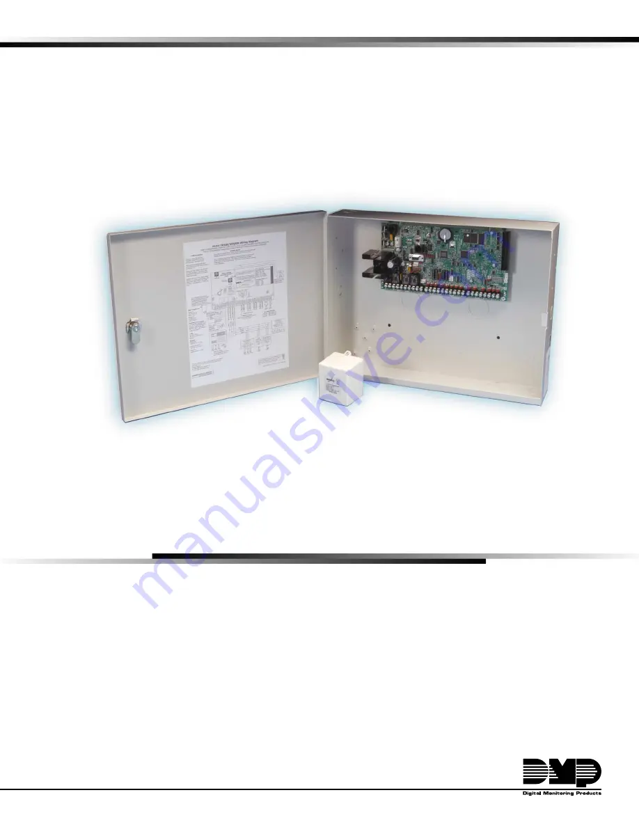
Page 13: ...e J10 J22 LX Bus Battery Start J23 J21 RS 232 Power LED J8 PROG J4 Tamper J16 Reset Out1 Out2 Outputs 3 6 J11 3 4 5 6 J2 J1 Ethernet R L X OVC Power LED Link LED Figure 3 XR500 XR500N in Model 350A En...
Page 14: ...increases DC voltage on the wire decreases Maximum number of LX Bus devices per 2 500 feet circuit is 40 For additional information refer to the 710 Installation Sheet LT 0310 and or the LX Bus Keypad...
Page 15: ...cutoff relay is pulled in automatically For more information refer to Figure 2 6 4 Battery Replacement Period DMP recommends replacing the battery every 3 to 5 years under normal use 6 5 Discharge Re...
Page 16: ...Qty ______x Qty ______x Qty ______x 30mA 2mA 20mA ______ ______ ______ 736P POPIT Interface Module Radionics Popex POPITs OctoPOPITs Qty ______x Qty ______x 25mA ___mA ______ ______ Qty ______x Qty _...
Page 17: ...stalled to the left of the XR500 XR500N enclosure to ensure Battery and AC wire separation 24 hours of standby power 4 5 Ah Batteries 7 Ah Batteries 7 7 Ah Batteries 9 Ah Batteries 18 Ah Batteries Max...
Page 18: ...Terminal 8 receives data from keypads and zone expansion modules It cannot be used for any other purpose 8 4 Terminal 9 GREEN Terminal 9 transmits data to keypads and zone expansion modules It cannot...
Page 19: ...esistance on zone Voltage on positive terminal Open over 1300 ohms over 2 0 VDC Normal 600 to 1300 ohms 1 2 to 2 0 VDC Short under 600 ohms under 1 2 VDC 10 3 Zone Response Time A condition must be pr...
Page 20: ...725 Hochiki SIJ 24 HD 3 NS6 220 HB 3 15 33 20 725 Hochiki DCD 190 DCD 135 HD 3 NS6 220 HB 3 15 33 16 725 Sentrol ESL 429AT 521B 521BXT 521NB 521NBXT S09A 6 5 20 12 715 715 8 715 16 9 10 Sentrol ESL 42...
Page 21: ...Color Output 1 normally closed Violet Output 1 common Gray Output 1 normally open Orange Output 2 normally closed Violet with white stripe Output 2 common White with gray stripe Output 2 normally ope...
Page 22: ...hen using J22 as an LX Bus connect a DMP Model 300 4 wire Harness to the J22 4 pin header labeled LX BUS This provides the rst 100 LX Bus zones numbered 500 599 No LX Bus Interface Card is required Re...
Page 23: ...onnector indicate network operation The top Activity LED flashes green to indicate the network traffic is good The bottom Link LED flashes yellow to indicate messages are being sent and received J3 Te...
Page 24: ...to the 893A Installation Sheet LT 0135 for complete information 18 4 Noti cation The user must not repair registered terminal equipment In case of trouble immediately unplug the device from the teleph...
Page 25: ...place the Reset jumper over both of the J16 pins to reset the panel AC 1 2 3 4 5 6 7 8 10 11 12 13 14 15 16 17 18 19 9 20 21 22 23 24 25 26 27 28 B BELLGND SMK GND RED YEL GRN BLK Z1 Z2 Z3 Z4 Z5 Z6 Z7...
Page 26: ...station phone number 20 5 Bypass Reports The Bypass Reports option must be programmed as YES for all UL burglary applications See the XR500 XR500N Programming Guide LT 0679 20 6 System Maintenance To...
Page 27: ...l be able to disarm that area UL 1023 Speci cations Household Burglar Alarm System Units 22 1 Audible Devices At least one listed audible device Ademco AB12M rated to operate over the voltage rate of...
Page 28: ...e installed in a UL AA application when NET communication is used The NET network check in time must be set from 01 to 06 minutes or AA This provides AA Central Station service When a dialer is requir...
Page 29: ...annot be less than 15 minutes See the XR500 XR500N Programming Guide LT 0679 25 6 Automatic Bell Test The Automatic Bell Test option must be programmed as YES See the XR500 XR500N Programming Guide LT...
Page 30: ...used 26 5 Grade A Bell A Grade A local audible signal appliance must be used such as Ademco AB12M bell and bell housing 26 6 Bank Safe and Vault XR500N only In addition to the requirements for Mercan...
Page 31: ...hone number unless that phone number is speci cally provided for that purpose 28 8 System Maintenance To ensure continuous satisfactory operation of any alarm system proper installation and regular ma...
Page 32: ...ours See the XR500 XR500N Programming Guide LT 0679 29 5 Local Protective Signaling Systems The DMP Model 865 866 or 867 Noti cation Circuit Module must be used on the bell circuit for detection of sh...
Page 33: ...d rated at 85 DB minimum must be used 30 3 Auxiliary Circuits At least one re alarm initiating device shall be used on the system If the voltage for the device is applied by the control unit the re al...
Page 34: ...to a maximum of twenty five 866 Modules on the XR500 XR500N panel All modules must be installed in a 340FC 349 or 350 enclosure connected by no more than 20 feet of conduit S 24 VDC 5 Amp Maximum Pow...
Page 35: ...es Install up to a maximum of twenty five 866 Modules by using the relay outputs available on the XR500 panel All modules must be installed in a 340FC 349 or 350 Enclosure connected by no more than 20...
Page 36: ...GND RED YEL GRN BLK Z1 Z2 Z3 Z4 Z5 Z6 Z7 Z8 Z9 Z9 Z10 Z10 AC B GND GND GND GND K6 K7 J3 J10 J22 Battery Start J23 J21 RS 232 J8 J4 Tamper J16 Reset J11 J2 J1 GND Fault A GND Fault B A1 A1 A2 A2 Zone A...
Page 37: ...ttery Start J23 J21 J8 PROG J4 Tamper J16 Reset J11 J2 J1 Cellular Transceiver Supervised Circuit S 1 2 3 4 5 6 Panel Auxiliary Power Terminal 7 Note 1 Note 1 Telco Jack Panel Common Terminal 10 Super...
Page 38: ...1 2 3 4 5 6 7 8 10 11 12 13 14 15 16 17 18 19 9 20 21 22 23 24 25 26 27 28 B BELL GND SMK GND RED YEL GRN BLK Z1 Z2 Z3 Z4 Z5 Z6 Z7 Z8 Z9 Z9 Z10 Z10 AC B GND GND GND GND K6 K7 J3 J10 J22 Battery Start...
Page 39: ...itional LX Bus Modules Red Yellow Green Black LX Bus Wiring TENS ONES TENS ONES Bell Relay Address Supervisory Address Each LX Bus Module must have its own independent address ranging from 00 to 99 A...
Page 40: ...B BELL GND SMK GND RED YEL GRN BLK Z1 Z2 Z3 Z4 Z5 Z6 Z7 Z8 Z9 Z9 Z10 Z10 AC B GND GND GND GND K6 K7 J3 J10 J22 Battery Start J23 J21 RS 232 J4 Tamper J16 Reset J11 J2 J1 R L X 12 VDC Relay 4 Relay 3 R...
Page 41: ...XR500 XR500N Installation Guide Digital Monitoring Products 35...
Page 42: ...CODE Enter your code number and press COMMAND The keypad display now shows ALARM SILENCE if your code allows Press the COMMAND key until SENSOR RESET appears in the display Press any top row key TROU...