background image

3


©2005 Digital Intelligence, Inc. 


Power Considerations 

UltraBlock is powered via the 5-pin DIN connector from the UltraBlock Power 
Supply.  

The device is turned on using the ON/OFF switch on the side of the unit.   

UltraBlock Cabling 

You should only select a single cable/interface to connect the UltraBlock to your 
PC.  Select EITHER a FireWire400 or USB connection on the UltraBlock. 

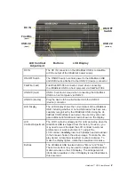
Diagnostic LED’s 

The DC IN LED indicates the unit is receiving power from the attached power 
supply. 

The “Host Detect” LED indicates the connected PC interface is properly 
detected. 

The Power LED indicates the unit is receiving power and the power switch has 
been turned on. 

The “Write Block” LED indicates the status of the write protect mode.  The LED 
is illuminated when the device is in Read-Only mode.  If the UltraBlock USB is 
attached to the PC via the FireWire interface it will flash when an attempted 
write is blocked.   

The “Activity” LED indicates device activity. 


Drivers 

No device specific drivers are required for the UltraBlock.  Full driver support is 
provided by the host operating system and/or interface controller (FireWire or 
USB Adapter).  Normally, the required drivers will automatically be loaded by 
the operating system.  (Note that Windows 98 does not natively support USB 
Storage Devices).  Refer to your Operating System, Motherboard, or Host 
Adapter manufacturer for additional driver related information. 

Cables 

Use only high quality FireWire or USB cables.  If you are connecting the 
UltraBlock to a USB 2.0 controller, be sure to use cables rated specifically for 
USB 2.0 transmission speeds. 

NOTE:   There is an important difference between the UltraBlock 
USB and other UltraBlock forensic bridges.  The UltraBlock IDE, 
UltraBlock SATA, and UltraBlock SCSI bridges can be switched 
between read-only (write-block) and read-write modes of opera-
tion, the UltraBlock USB is permanently configured for read-only 
(write-blocked) operation. 

Summary of Contents for UltraBlock USB

Page 1: ...U S E R G U I D E UltraBlock USB I M P O R T A N T R E A D M E F I R S T...

Page 2: ......

Page 3: ...or altered unless such repair modification of alteration is authorized in writing by DI or 2 the serial number of the product is defaced or missing Products and corporate names appearing in this manua...

Page 4: ...ages so the above limitation or exclusion may not apply to you DI reserves the right to modify its warranty statement at any time in its sole discretion DI will be obligated to honor any such warranty...

Page 5: ...tions 3 UltraBlock Cabling 3 Diagnostic LED s 3 Drivers 3 Cables 3 Attaching the UltraBlock USB 4 Changing USB Devices 4 Disconnecting the UltraBlock USB 4 LCD Display 5 Modifying your UltraBlock Capa...

Page 6: ...a hardware based write blocker that allows a USB mass storage device i e flash drives thumb drives external USB hard drives etc to be connected to a personal computer for forensic image acquisition a...

Page 7: ...shipped from the factory However you may need or want to adjust the LCD contrast to suit your preferences or work environment To adjust the LCD contrast carefully insert a 0 phillips head screwdriver...

Page 8: ...ill flash when an attempted write is blocked The Activity LED indicates device activity Drivers No device specific drivers are required for the UltraBlock Full driver support is provided by the host o...

Page 9: ...otify the operating system to complete any pending transfer operations so the device can be safely disconnected 2 Turn the UltraBlock Off 3 Remove existing USB device Disconnect the USB mass storage d...

Page 10: ...Detect LEDs flash ON in sequence At the end of the diagnostic the UltraBlock will illuminate the Write Block LED MAIN MENU After the power ON diagnostic is complete the display defaults to the Status...

Page 11: ...ognized the Status display will automatically rotate among the following informational screens NOTE Some USB mass storage devices do not return a manufacturer or model product name In these cases the...

Page 12: ...e USB device Pr oduc t na me Cr uz e r Mi c r o Serial number of the USB device Se r i a l SNDKAAC6 C4 2 A2 5 D0 Firmware Revision of the USB device Fi r mwa r e r e v 0 2 The speed of the USB device...

Page 13: ...his information may assist technical support personnel Internal device speed HS FS LS Dev or Hub and device mfg name De v 1 HS De v 1 8 Sa nDi s k Cor por a t Device model name De v 1 HS De v 2 8 Cr u...

Page 14: ...t confuse this with information about a USB device which may be attached to the bridge UltraBlock USB model name Ta bl e a u T8 USB For e ns i c Br i dge Firmware timestamp T8 J ul 2 6 2 0 0 5 f w 1 5...

Page 15: ...vice is write protected If the switch is ON the code page indicates the device was not write protected The following table summarizes the recommended configuration depending on the operating system yo...

Page 16: ...e usually not as reliable as the direct to the circuit board USB connectors typically found on the motherboard or hub If you have trouble using a front panel USB connection try using the rear USB conn...

Page 17: ...tached NTFS FAT file system effectively resulting in an NTFS file system for which no drive letter is assigned This condition is a function of the Windows NT 2K XP operating system and happens specifi...

Page 18: ...ock enabled Activity USB device detect Host detect LCD Contrast Control LCD contrast adjustment via externally accessible potentiometer Compatibility USB Device USB devices must conform to the USB Mas...

Page 19: ......

Page 20: ...2005 Digital Intelligence Inc All rights reserved w w w d i g i t a l i n t e l l i g e n c e c o m Digital Intelligence Inc 17165 W Glendale Drive New Berlin WI 53151 P 262 782 3332 F 262 782 3331...

Reviews: