background image

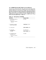
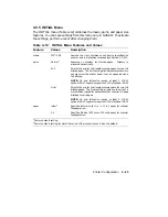
4.3.3 NVRAM (Nonvolatile Random-Access Memory)

The printer can communicate with many systems using the factory default
settings in ROM, but you may have to change values to accommodate your
particular application or host computer. NVRAM allows those changes to
be saved in a nonvolatile memory so that they are available each time you
power on the printer. In nonvolatile memory the selected values are not
cleared when the printer is powered off or reset. Selections are saved in
NVRAM until you change them. To save values in NVRAM while in Menu
Mode, use the procedure shown in Table 4–4.

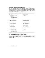
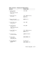
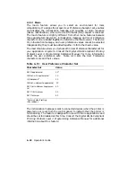
Table 4–4: Saving Values in NVRAM

Operation

Display Reads

1. Press

On Line

to place the

printer off line.

— The On Line indicator

shuts off.

00 READY

2. Press

Menu

to place the

printer in Menu Mode.

FONT/FEED LAYOUT

3.

Press

/

twice.

SAVE–>NVRAM LOAD

4.

Press

r

Enter

to save the values
in NVRAM.

OK (momentarily)

#

SAVE–>NVRAM LOAD

5.

Press

On Line

to place

the printer on line.

— The On Line indicator

lights.

00 READY

Printer Configuration

4–9

Summary of Contents for DEClaser 2100 plus

Page 1: ...DEClaser 2100 plus Printer Operator s Guide Order Number EK DECLA OG 001 Digital Equipment Corporation Maynard Massachusetts...

Page 2: ...hts reserved Printed in U S A The Reader s Comments form at the end of this document requests your critical evaluation to assist in preparing future documentation The following are trademarks of Digit...

Page 3: ...the equipment off and on the user is encouraged to try to correct the interference by one or more of the following methods Reorient the receiving antenna Relocate the computer or peripheral with respe...

Page 4: ...2 8 2 5 2 Selecting the Rear Output Tray Faceup Print 2 9 2 6 Loading Paper 2 10 2 6 1 Adding Paper to the Cassette 2 11 2 7 Loading Preprinted Media 2 15 2 8 Feeding Media Manually 2 15 2 8 1 Manuall...

Page 5: ...laying Menu Values 4 5 4 3 Printer Configuration Memory 4 6 4 3 1 Operating Memory 4 7 4 3 2 ROM Read Only Memory 4 8 4 3 3 NVRAM Nonvolatile Random Access Memory 4 9 4 3 4 RAM Random Access Memory 4...

Page 6: ...Envelopes 5 7 5 3 Transparency Specifications 5 8 5 3 1 Special Considerations When Printing Transparencies 5 8 5 4 Label Specifications 5 9 5 4 1 Special Considerations When Printing on Labels 5 10...

Page 7: ...ing the Ozone Filter 7 36 Chapter 8 Service 8 1 Digital Equipment Corporation Services 8 1 Appendix A DEClaser Printer Quick Reference Guide A 1 Positioning Controls A 3 A 2 Margins and Spacing A 6 A...

Page 8: ...ew 1 9 1 5 Operating Space Side View 1 9 2 1 Engine Test Print 2 39 2 2 Test Print A 2 42 2 3 Test Print B 2 46 2 4 Font List 2 49 3 1 Control Panel 3 1 4 1 Sample of a Menu 4 1 4 2 Menu Display 4 5 4...

Page 9: ...Functions 3 2 3 2 Entering Keypad Mode 3 4 3 3 Keypad Functions Keypad Mode 3 4 4 1 Entering Menu Mode 4 2 4 2 Keypad Functions Menu Mode 4 3 4 3 Recalling Factory Default Values from ROM 4 8 4 4 Sav...

Page 10: ...Messages 6 4 6 4 Software Error Messages 6 6 6 5 Common Operating Problems 6 9 8 1 Questions to Consider Before You Call 8 2 A 1 DECVPFS Numeric Parameters A 9 A 2 Character Set Identification A 17 B...

Page 11: ...e loading capability Support for both serial and parallel interfaces Convenient user maintenance one replaceable supply cartridge Ability to print on envelopes Manual feeding capability The following...

Page 12: ...ng print density It also describes how to manually feed print media Chapter 3 The Control Panel covers the use of the printer s control panel It describes operational information about the indicators...

Page 13: ...information section at the end of this guide The ordering number for the documentation is EK DECLA DK The documentation set consists of one of each of the following DEClaser 2100 plus Printer Installa...

Page 14: ...rs Reference Manual for ReGIS and Tektronix 4010 4014 AA PBWFA TE This manual is for programmers who need to convert ReGIS or Tektronix 4010 4014 documents to PostScript for printing on PostScript pri...

Page 15: ...pecial instruction related to a procedural step For example 1 Add paper to the cassette by placing it into the left side first being sure the paper is inserted below the paper guide and maximum height...

Page 16: ...emissions and laser beam light exposure Read the following information to become familiar with ozone and laser safety Ozone Safety Ozone is a colorless gas O3 that is a by product of the electrophotog...

Page 17: ...ts on August 2 1976 These regulations apply to laser products manufactured beginning August 1 1976 Compliance is mandatory for products marketed in the United States The label shown in Figure 1 indica...

Page 18: ...nctions This chapter also provides information about the operating space required to perform day to day printing operations 1 1 Functions of the Printer Components Figures 1 1 through 1 3 show the pri...

Page 19: ...Figure 1 1 Components Front Right Side View MLO 004826 1 2 Operator s Guide...

Page 20: ...est Print 5 Control Panel The control panel consists of a message display indicator lights and a keypad The control panel provides information on printer status and can be used to perform certain prin...

Page 21: ...Figure 1 2 Components Rear Left Side View MLO 004827 1 4 Operator s Guide...

Page 22: ...ing and using the rear output tray 3 Memory Board Access Cover Additional RAM random access memory can be added to the printer in 1 2 or 3 MB capacities This access cover allows you to easily install...

Page 23: ...Figure 1 3 Components Inside the Printer MLO 004828 1 6 Operator s Guide...

Page 24: ...each time a new EP S cartridge is installed Each EP S cartridge comes with replacement instructions or you can refer to Section 7 3 for more information about replacing the roller cleaner 4 EP S Cart...

Page 25: ...he transfer corona wire 7 Paper Transfer Guide Ensures that paper is properly routed from the cassette to the transfer corona assembly You can also open the paper transfer guide to access paper jams t...

Page 26: ...Figure 1 4 Operating Space Top View MLO 004346 Figure 1 5 Operating Space Side View MLO 004844 Printer Components 1 9...

Page 27: ...asks such as adding paper selecting an output tray or powering the printer on and off This chapter also covers manual feed operation for all print media 2 1 Powering the Printer On Power the printer o...

Page 28: ...READY DEC only if you are using Digital s ANSI Compliant Printing Protocol level 3 PPL3 which is the factory default setting If you are using an optional protocol such as PostScript or CaPSL the displ...

Page 29: ...s paper jams and loss of data Powering the printer off while the Data indicator is on causes the data in the print buffer to be lost 2 Press the power switch on the back of the printer to the O OFF po...

Page 30: ...Opening the Top Cover Open the top cover using the following procedure 1 Press the release button forward and then down The top cover releases and opens slightly Fig 2 3 MLO 004830 2 4 Operator s Gui...

Page 31: ...2 4 MLO 004831 p The halfway position is intended for Replacing the EP S cartridge Adjusting the print density dial p The upright position is intended for Replacing the fixing roller cleaner Replacing...

Page 32: ...sing the Top Cover Close the top cover using the following procedure 1 Gently lower the cover and push down on the hand grip until the cover latches securely in place Fig 2 5 MLO 004366 2 6 Operator s...

Page 33: ...closed printed paper is delivered facedown to the top output tray This allows your print job to be collated in the correct page order When the rear output tray is opened printed paper is delivered fac...

Page 34: ...pen the printer sends printed paper facedown to the top paper tray If the rear output tray is open use the following procedure to select the top output tray 1 Fold in the extension tray Fig 2 7 MLO 00...

Page 35: ...the Rear Output Tray Faceup Print Use the following procedure to select the rear output tray 1 Open the rear output tray Fig 2 9 MLO 004835 2 Fold out the extension tray Fig 2 10 MLO 004836 Operating...

Page 36: ...nvelopes transparencies and labels See Section 2 8 for information about feeding print media manually Here are some general guidelines to follow about the paper used in the printer Use only high quali...

Page 37: ...EADY or 11 PAPER OUT before removing the paper cassette CAUTION Do not remove the paper cassette while the printer is printing Removing the paper cassette during printing can damage the printer 2 Remo...

Page 38: ...t being sure it is inserted below the paper guide and maximum height guard p To prevent paper jams do not load too much paper into the cassette Leave a small amount of space between the paper and the...

Page 39: ...5 Replace the cover on the cassette Fig 2 14 MLO 004840 Operating Information 2 13...

Page 40: ...6 Insert the paper cassette into the printer The Alarm indicator shuts off The display reads 00 READY Fig 2 15 MLO 004370 2 14 Operator s Guide...

Page 41: ...automatically from the cassette You must feed the following print media into the printer manually Nonstandard sized papers from 100 mm x 190 mm 3 9 in x 7 in to 216 mm x 356 mm 8 in x 14 in that do n...

Page 42: ...ESC 8 SP J ESC 99 v Table 2 1 Legal Size Coding Example Escape Sequence Name of Command Description ESC 7 SP I SSU Size Select Unit Units can be pixels deci points or centipoints This example uses pix...

Page 43: ...ually feed paper labels and transparencies Refer to Chapter 5 for the specifications required for print media Be sure the printer is set up to print on the media size you are using either through the...

Page 44: ...2 Fold out the extension tray Fig 2 17 MLO 004836 2 18 Operator s Guide...

Page 45: ...0 READY The manual feed mode selection is now stored in operating memory 5 Press On Line to place the printer back on line The On Line indicator lights 6 Send data from the host computer to the printe...

Page 46: ...ies from the rear output tray as each one is printed This prevents them from sticking together Fig 2 19 MLO 004842 9 Wait until PF FEED xxx is displayed and repeat step 8 p Continue feeding paper unti...

Page 47: ...il the display reads FEEDER Cass After about 3 seconds the display will read 00 READY The cassette feed mode selection is now stored in operating memory 12 Press On Line to place the printer back on l...

Page 48: ...14 Close the rear output tray Fig 2 21 MLO 004834 2 22 Operator s Guide...

Page 49: ...leading edge of the paper may cause the paper to wrinkle misprint or jam Flatten out any curl on the paper before making a duplex print If the curl cannot be flattened completely place the paper so th...

Page 50: ...1 Open the rear output tray Fig 2 23 MLO 004835 2 Fold out the extension tray Fig 2 24 MLO 004836 2 24 Operator s Guide...

Page 51: ...ter about 3 seconds the display will read 00 READY The manual feed mode selection is now stored in operating memory 5 Press On Line to place the printer back on line The On Line indicator lights 6 Sen...

Page 52: ...dth of the paper Fig 2 25 MLO 004841 8 Insert a single sheet of paper into the printer until it stops The paper is automatically fed into the printer The printed paper is sent to the rear output paper...

Page 53: ...ex printing go to step 6 after the display reads 00 READY If you have finished duplex printing go to step 11 11 Press On Line to place the printer off line The On Line indicator shuts off 12 Press Man...

Page 54: ...14 Fold in the extension tray Fig 2 28 MLO 004833 15 Close the rear output tray Fig 2 29 MLO 004834 2 28 Operator s Guide...

Page 55: ...our files to print in a particular area Appendix A contains a listing of DEClaser 2100 plus commands and programming information for the experienced programmer For detailed programming information nec...

Page 56: ...1 Open the rear output tray Fig 2 30 MLO 004835 2 Fold out the extension tray Fig 2 31 MLO 004836 2 30 Operator s Guide...

Page 57: ...ter about 3 seconds the display will read 00 READY The manual feed mode selection is now stored in operating memory 5 Press On Line to place the printer back on line The On Line indicator lights 6 Sen...

Page 58: ...width of the envelope Fig 2 32 MLO 004846 8 Insert a single envelope into the printer until it stops The envelope is automatically fed into the printer The printed envelope is sent to the rear output...

Page 59: ...lightly with toner the print density dial can be reset to increase the density lower number on the dial to correct the fogging problem See Section 2 11 for information about setting the print density...

Page 60: ...14 Fold in the extension tray Fig 2 34 MLO 004833 15 Close the rear output tray Fig 2 35 MLO 004834 2 34 Operator s Guide...

Page 61: ...le number lightest setting that gives you acceptable print quality For most applications a print density setting of 7 can be used to produce high quality print and extend the life of the cartridge NOT...

Page 62: ...triangle p Numbers on the dial are displayed in increments of 2 p Number 1 is the darkest setting number 9 is the lightest setting p Although the printer is shipped with the dial set to number 5 you...

Page 63: ...4 Close the top cover by gently lowering the cover and pushing down on the hand grip until the cover latches securely in place Fig 2 39 MLO 004366 Operating Information 2 37...

Page 64: ...y across the entire page with no faded areas If the print quality is poor see Section 6 6 for help to correct the problem If the Engine Test Print will not print there may be a problem with the printe...

Page 65: ...Figure 2 1 Engine Test Print Fig 2 40 MLO 004525 Operating Information 2 39...

Page 66: ...inter with a ballpoint pen The printer enters the offline state The Alarm indicator lights while the page is printing The display reads 15 ENGINE TEST while the page is printing The printer remains in...

Page 67: ...2 13 Printing Test Print A Test Print A Figure 2 2 lists the current printer settings along with information such as total page count and the amount of free memory available Operating Information 2 41...

Page 68: ...Figure 2 2 Test Print A Fig 2 42 MLO 004851 2 42 Operator s Guide...

Page 69: ...he name of installed emulation cartridges PostScript cartridges or font cartridges and their location left or right font cartridge slot Page Count Indicates the total number of pages printed to date F...

Page 70: ...A Operation Display Reads 1 Press On Line to place the printer off line The On Line indicator shuts off 00 READY 2 Press Test Font once Test Print A prints 05 TEST PRINT A 00 READY 3 Press On Line to...

Page 71: ...2 14 Printing Test Print B Test Print B Figure 2 3 contains sample printouts of the character sets that can be examined for print quality Operating Information 2 45...

Page 72: ...Figure 2 3 Test Print B Fig 2 43 MLO 004852 2 46 Operator s Guide...

Page 73: ...Operation Display Reads 1 Press On Line to place the printer off line The On Line indicator shuts off 00 READY 2 Press and hold down Test Font for about 3 seconds The test page prints continuously 01...

Page 74: ...2 15 Printing the Font List Figure 2 4 shows the Font List which contains a listing of all the available character sets in the printer along with a sample of the available fonts 2 48 Operator s Guide...

Page 75: ...Figure 2 4 Font List Fig 2 44 MLO 004853 Operating Information 2 49...

Page 76: ...Protocol Level 3 Programming Reference Manual and the Digital ANSI Compliant Printing Protocol Level 3 Programming Supplement Use the procedure in Table 2 5 to print the font list Table 2 5 Printing...

Page 77: ...rence Manual NOTE If the file does not fill the page buffer completely the remaining data can be printed by pressing On Line to place the printer off line and then pressing Form Feed to print the part...

Page 78: ...sizes To clear data in the print buffer To invoke features in the INITIAL menu To enter and exit Control Representation Mode Use the procedure in Table 2 7 to perform a soft reset Table 2 7 Resetting...

Page 79: ...8 to select Emulation Mode Table 2 8 Selecting Emulation Mode Operation Display Reads 1 Press On Line to place the printer off line The On Line indicator goes off 00 READY 2 Press and hold Menu for ab...

Page 80: ...keypad allows you to perform certain printer functions such as printing test pages or configuring the printer menus This chapter explains the features and uses of the control panel The layout of the c...

Page 81: ...Keypad Mode See Section 4 1 for information about using the keypad in Menu Mode On Line indicator green Works in conjunction with On Line to indicate when the printer is on line or off line see On Lin...

Page 82: ...ts A beep sounds when the printer first senses an alarm condition The message display works in conjunction with the Alarm indicator by showing the type of error condition For example 12 PRINTER OPEN T...

Page 83: ...ypad Mode Operation Display Reads 1 Press On Line to place the printer off line The On Line indicator goes off The keypad is now in Keypad Mode 00 READY Table 3 3 describes the keypad functions in Key...

Page 84: ...er and displaying the type of error on the control panel When this happens you may elect to note the problem and then continue printing by pressing Error Skip Pressing Error Skip bypasses these errors...

Page 85: ...NT FEED LAYOUT Refer to Section 4 1 for more information about the Menu Mode Pressing Menu for about 4 seconds activates Emulation Mode when an optional emulation cartridge is installed See Section 2...

Page 86: ...software You configure the DEClaser 2100 plus printer by selecting an appropriate set of values from a group of printer setup menus You make these selections while the printer is in Menu Mode Once va...

Page 87: ...d only from the control panel 4 1 Entering Menu Mode You configure the printer by selecting certain parameters features and values while in Menu Mode When the printer is in Menu Mode the keys labeled...

Page 88: ...4 2 Keypad Functions Menu Mode Key Function Performs two functions Scrolls the menus and features to the right Increases numeric values Performs two functions Scrolls the menus and features to the le...

Page 89: ...tly as they do on Test Print A For example if you are using Digital s ANSI Compliant Printing Protocol the first menu listed on Test Print A is the FEEDER menu but on the message it is displayed as th...

Page 90: ...e or initial capitals with the selected item shown in bold type for clarification For example FONT FEED LAYOUT or offsetX offsetY 4 2 2 Displaying Menu Values Menu values are scrolled to the right and...

Page 91: ...on Test Print A Configuration memory can be accessed only from the menus to set up the operational parameters of the printer You can save new values temporarily in RAM but they are cleared when the p...

Page 92: ...y and become part of the printer settings that are currently in use Figure 4 3 shows the operational flow between the different types of memory Figure 4 3 Operating Memory ROM NVRAM RAM Load ROM Save...

Page 93: ...eceives a reset command or is powered off If you want to retain the default values you must save them in NVRAM see Section 4 3 3 Table 4 3 Recalling Factory Default Values from ROM Operation Display R...

Page 94: ...cleared when the printer is powered off or reset Selections are saved in NVRAM until you change them To save values in NVRAM while in Menu Mode use the procedure shown in Table 4 4 Table 4 4 Saving Va...

Page 95: ...s On Line to place the printer off line The On Line indicator shuts off 00 READY 2 Press Menu to place the printer in Menu Mode FONT FEED LAYOUT 3 Press three times SAVE RAM SAVE 4 Press r Enter to sa...

Page 96: ...l Flow Chart Place the Printer Off Line Enter Menu Mode Select the Menu Select the Feature Change the Value Settings Save Settings in Memory Place the Printer Back On Line Save No Yes MLO 004946 Print...

Page 97: ...e Test Print A to verify the changes you make Print a copy of Test Print A before beginning this example Section 2 13 Be sure that all printing has stopped and the display reads 00 READY before you ma...

Page 98: ...ture offsetY autoNL o 9 Press r Enter to select the offsetY feature offsetY 0 0 10 Press until the value equals 10 0 NOTE The value decreases in steps of 0 5 offsetX 10 0 11 Press r Enter to enter the...

Page 99: ...indicator lights 00 READY Verification To verify that the offset distances have been changed print a copy of Test Print A and compare it with the copy made before the changes Verify the changes by co...

Page 100: ...Figure 4 5 TEST PRINT A Verification MLO 004857 Note This does not exist in the art package however it is the art that I need I don t want 4851 here Printer Configuration 4 15...

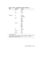
Page 101: ...Features Values FEEDER feeder Cass 1 Manual LAYOUT offsetX2 10 0 0 01 10 0 offsetY2 10 0 0 01 10 0 autoNL ON1 OFF COPY copy 011 99 COMMAND message2 English1 Finnish French German Italian Japan Norway...

Page 102: ...48001 9600 19200 rsmode4 8S1 8SS 7OS 7ES 7OSS 7ESS 8OS 8ES dtr4 Fix H1 Ready H xon xoff4 ON1 OFF etx ack4 OFF1 ON 1Factory default setting 2Cannot be selected using a command from the host Selectable...

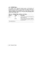
Page 103: ...nual Feed key For more information about manual feed operation see Section 2 8 Table 4 8 shows the features and values of the FEEDER menu Table 4 8 FEEDER Menu Features and Values Feature Values Descr...

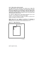
Page 104: ...the page An offset of 10 0 is approximately 1 1 in offsetY 10 0 0 01 10 0 Determines the offset distance from the top and bottom of the page An offset of 10 0 is approximately 1 1 in autoNL ON1 When t...

Page 105: ...the print on the page Test Print B is typically used when adjusting the offset positions You cannot set offset positions using escape sequences from the host computer You must select them from the co...

Page 106: ...Figure 4 7 shows sample printouts of Test Print A that use different offset values Figure 4 7 Offset Printout Samples MLO 004858 Printer Configuration 4 21...

Page 107: ...Menu The COMMAND menu Table 4 11 lets you display messages in your native language Three types of messages are displayed in the desired language status operator call and error Service call messages a...

Page 108: ...iminates complex errors but may slow the printer down if not all pages require a full bitmap NOTE A4 and letter size require at least 1 MB of optional RAM Legal size requires 2 MB of optional RAM Dual...

Page 109: ...r application or system Consult the Digital ANSI Compliant Printing Protocol Level 3 Programming Reference Manual for more information about the user preference sets Table 4 13 lists the User Preferen...

Page 110: ...require the printer to identify itself as an LN03 printer For example the DECmate word processing system requires an LN03 device identification The device identification values are shown in Table 4 15...

Page 111: ...5 4 Paper Size paper The paper size feature determines the printable area on the page It is only used in manual feed mode when no other command has been received to specify paper size See Section 2 8...

Page 112: ...rface all other features in the interface menu are disabled Optional I O When an option is plugged into the I O port the I O option will appear in the i f menu baud2 300 600 1200 2400 48001 9600 19200...

Page 113: ...face selection i f feature selects the type of interface used to communicate with the host computer and enables video mode The serial or parallel interface must match the interface used by the host co...

Page 114: ...match the format of the host computer in order for the printer and the host to communicate 4 5 6 4 Data Terminal Ready dtr The data terminal ready dtr feature uses hardware to regulate the flow of da...

Page 115: ...The etx ack feature also uses software to regulate the flow of data to the input buffer by exchanging signals with the host computer It is recommended that this feature be enabled by systems that supp...

Page 116: ...lways print test samples of the paper you want to use This is particularly important when you are printing on chemically treated or coated paper such as preprinted forms or colored paper The inks and...

Page 117: ...able 5 1 Cassette Feed Paper Sizes Paper Size Dimensions A4 210 mm x 297 mm Executive 7 in x 10 in Letter 8 in x 11 in Legal 8 in x 14 in Manual Feed Paper and Envelope Sizes Manual feed operation can...

Page 118: ...011 ohm cm surface Cotton rag content 25 maximum 5 1 1 Special Considerations When Printing on Paper Because of the way laser printers print and bond toner to the paper you must observe some special r...

Page 119: ...specifications as paper see Table 5 2 In addition the following types of envelopes cannot be used with the printer Envelopes with sealing flaps that are open Fig 5 1 MLO 005731 NOTE I don t know why...

Page 120: ...g edges Fig 5 2 MLO 005729 NOTE I don t know why the MLO numbers on this art changed Envelopes with three or more layers of paper at the leading and trailing edges Fig 5 3 MLO 005732 NOTE I don t know...

Page 121: ...nt windows Fig 5 4 MLO 005730 NOTE I don t know why the MLO numbers on this art changed Envelopes that have clasps snaps or strings Fig 5 5 MLO 005733 NOTE I don t know why the MLO numbers on this art...

Page 122: ...ter the proper print coordinates to print the addresses See Section 2 10 for more information about printing on envelopes Printing in the 15 mm 3 5 in border around the envelope may cause print qualit...

Page 123: ...ness 0 095 mm to 0 115 mm Heat tolerance 200 C 392 F for 0 1 second 5 3 1 Special Considerations When Printing Transparencies Observe the following requirements when printing on transparencies Transpa...

Page 124: ...ust also be able to meet the heat tolerance specification of 200 C 392 F for at least 0 1 second Figure 5 1 shows the types of labels that are unacceptable CAUTION Exposed adhesive on labels can cause...

Page 125: ...ems Follow the recommendations in this section on paper storage and handling to reduce the possibility of printer jams and misfeeds 5 5 1 Paper Handling Observe the following requirements when handlin...

Page 126: ...rl is present fan the paper in the opposite direction of the curl to remove as much of the curl as possible Follow the instructions in Chapter 2 to properly load paper 5 5 2 Paper Storage Observe the...

Page 127: ...splay when they occur The corrective action to take is listed in the appropriate table as follows Topic Table Printer Status Messages Table 6 2 Operator Call Messages Table 6 3 Software Error Messages...

Page 128: ...formatting errors may repeat when the printer is receiving additional communications data When this happens you may need to repeat the error skip procedure several times 6 2 Printer Status Messages P...

Page 129: ...is being reset Section 2 17 04 TEST STOP Test printing has stopped 05 TEST PRINT A Test Print A is being printed Section 2 13 06 FONT LIST A Font List A is being printed Section 2 15 15 ENGINE TEST Th...

Page 130: ...12 PRINTER OPEN The top cover of the printer is open Close the top cover Section 2 4 13 PAPER JAM Paper is jammed inside the printer Remove jammed paper from the printer Section 6 7 14 NO EP CART The...

Page 131: ...printer PF FEED LETTER Feed letter size paper Manually feed letter size paper into the printer PF FEED LEGAL Feed legal size paper Manually feed legal size paper into the printer PF FEED EXEC Feed ex...

Page 132: ...r devices that are connected such as print servers all have the same type of handshaking protocol enabled 23 MEMORY FULL Memory cannot accept additional downline load ing of fonts into memory Clear fo...

Page 133: ...problem continues call your Digital service representative Chapter 8 FE FONT REMOVAL A font cartridge has been removed from the printer Power off the printer and install the font cartridge before powe...

Page 134: ...Problems Table 6 5 lists common operating problems and their possible solutions Follow the corrective actions in the order in which they are listed Check the table to solve printer problems before ca...

Page 135: ...onnections at the printer and at the wall outlet NO PRINTOUT The message display reads 00 READY The interface cable to the host is not connected properly Check the cable connections at the printer and...

Page 136: ...transfer corona wires are dirty Clean the primary and transfer corona wires see Section 7 1 2 and Section 7 1 3 The primary corona wire is faulty Replace the EP S cartridge Section 7 3 The transfer c...

Page 137: ...e vertical pitch setting is incorrect Correct the vertical pitch setting in your application program The print is skewed The print medium is not the recommended type See Chapter 5 for print media spec...

Page 138: ...aper jams you should follow the instructions for proper paper selection storage and loading as outlined in Chapter 5 To ensure that you are loading paper in the tray properly see Section 5 5 1 for the...

Page 139: ...r jam is cleared and printing is resumed the DEClaser 2100 plus printer automatically reprints the page that jammed 6 7 1 Top and Output Paper Tray Paper Jams Use the following procedure to clear pape...

Page 140: ...1 Open the top cover by pressing the release button forward and then down The top cover will release and open slightly Fig 6 2 MLO 004891 6 14 Operator s Guide...

Page 141: ...en Fig 6 3 MLO 004868 3 Push the tab on the fixing assembly back to release the paper WARNING Be careful when accessing areas inside the printer because the fixing assembly may be hot Fig 6 4 MLO 0048...

Page 142: ...4 Remove the jammed paper from the printer by pulling it out from the output tray Fig 6 5 MLO 004892 6 16 Operator s Guide...

Page 143: ...ip until the cover latches securely in place The printer initializes recycles The Alarm and Data indicators shut off The message display reads 00 READY Fig 6 6 MLO 004366 6 Press On Line to place the...

Page 144: ...re to clear paper jams from the paper feed transfer and fixing assembly areas 1 Open the top cover by pressing the release button forward and then down The top cover will release and open slightly Fig...

Page 145: ...ift the transfer guide green handle to release the paper and remove the paper from the printer p If the jammed paper did not reach the feed area remove the cassette and pull the paper out from the cas...

Page 146: ...ush the green tab on the fixing assembly down to release the paper and remove the paper from the printer WARNING Be careful when accessing areas inside the printer because the fixing assembly may be h...

Page 147: ...p until the cover latches securely in place The printer initializes recycles The Alarm and Data indicators shut off The message display reads 00 READY Fig 6 11 MLO 004366 6 Press On Line to place the...

Page 148: ...the ozone filter 7 1 Cleaning the Printer Keeping the printer clean helps ensure optimum print quality because stray paper dust and toner can adversely affect the voltage levels placed on the corona w...

Page 149: ...r and paper feed areas inside the printer using the following procedure 1 Be sure the printer is not printing and the display reads 00 READY 2 Press the power switch on the back of the printer to the...

Page 150: ...3 Press the release button forward and then down The top cover releases and opens slightly Fig 7 2 MLO 004830 4 Lift the top cover open Fig 7 3 MLO 004868 Maintenance 7 3...

Page 151: ...e paper feed area black plastic clean with a cloth dampened with water WARNING Be careful when accessing areas inside the printer because the fixing assembly may be hot Fig 7 4 MLO 004871 7 4 Operator...

Page 152: ...ms clean in the transfer area with the dampened cloth The movable transfer guide with green handle and clear plastic strip The metal transfer roller The silver colored metal transfer guide Fig 7 5 MLO...

Page 153: ...7 Gently close the top cover by pushing down on the hand grip until the cover locks into place Fig 7 6 MLO 004366 7 6 Operator s Guide...

Page 154: ...A dirty primary corona wire can cause black streaking to occur on the paper and should be cleaned to correct this problem 1 Be sure the printer is not printing and the display reads 00 READY 2 Press t...

Page 155: ...3 Press the release button forward and then down The top cover releases and opens slightly Fig 7 8 MLO 004830 4 Open the top cover halfway Fig 7 9 MLO 004848 7 8 Operator s Guide...

Page 156: ...from the top cover Fig 7 10 MLO 004890 6 Remove the wire pin cleaner from the inside of the printer WARNING Be careful when removing the wire pin cleaner from the printer because the fixing assembly m...

Page 157: ...lot CAUTION Do not insert the brush end of the wire pin cleaner into the slot Inserting the brush end can damage the corona wire Fig 7 12 MLO 004875 8 Move the cleaner in the slot from side to side th...

Page 158: ...9 Return the wire pin cleaner to its storage location in the printer Fig 7 14 MLO 004873 10 Install the EP S cartridge into the top cover Fig 7 15 MLO 004889 Maintenance 7 11...

Page 159: ...11 Gently close the top cover by pushing down on the hand grip until the cover locks into place Fig 7 16 MLO 004366 7 12 Operator s Guide...

Page 160: ...place the EP S cartridge but you may find it necessary to clean them between cartridge replacements if you experience problems with print quality NOTE You will need a dry cotton swab such as the one s...

Page 161: ...3 Press the release button forward and then down The top cover releases and opens slightly Fig 7 18 MLO 004830 4 Lift the top cover open Fig 7 19 MLO 004868 7 14 Operator s Guide...

Page 162: ...move the wire pin cleaner from the inside of the printer WARNING Be careful when removing the wire pin cleaner from the printer because the fixing assembly may be hot Fig 7 20 MLO 004873 Maintenance 7...

Page 163: ...oove using the brush end of the cleaner CAUTION You must lift the brush over the separation wires as you clean along the groove Be careful not to break the wires as you clean the discharging pins Fig...

Page 164: ...7 Return the wire pin cleaner to its storage location in the printer Fig 7 22 MLO 004873 Maintenance 7 17...

Page 165: ...cotton swab CAUTION The corona wire and nylon separation wires are fragile Do not press down too hard on the wires Fig 7 23 MLO 004877 9 Gently close the top cover by pushing down on the hand grip un...

Page 166: ...he print density adjustment dial to the highest number possible lightest setting that gives you acceptable print quality The higher setting reduces the amount of toner used For most applications the d...

Page 167: ...ig 7 25 MLO 004362 Reinstall the cartridge and try printing If the toner low message does not appear or printing is acceptable the cartridge will last for a while longer If the toner low message remai...

Page 168: ...ctions that come with the cartridge or use the following procedure 1 Be sure the printer is not printing and the display reads 00 READY 2 Press the power switch on the back of the printer to the O OFF...

Page 169: ...3 Press the release button forward and then down The top cover will release and open slightly Fig 7 27 MLO 004830 4 Open the top cover to its halfway position Fig 7 28 MLO 004848 7 22 Operator s Guide...

Page 170: ...5 Remove the EP S cartridge by pulling it out from the top cover p Open the top cover to its full upright position after removing the cartridge Fig 7 29 MLO 004890 Maintenance 7 23...

Page 171: ...6 Open the green fixing assembly cover WARNING The fixing assembly may be hot Be careful when accessing the fixing unit Fig 7 30 MLO 004354 7 24 Operator s Guide...

Page 172: ...xing roller cleaner from the fixing assembly p Discard the used fixing roller cleaner Fig 7 31 MLO 004879 8 Wipe the fixing roller with the cleaning pad on the end of the new cleaner Fig 7 32 MLO 0043...

Page 173: ...9 Peel off the cleaning pad and discard it Fig 7 33 MLO 004356 10 Insert the new cleaner into the fixing assembly Fig 7 34 MLO 004357 7 26 Operator s Guide...

Page 174: ...11 Close the fixing assembly cover NOTE The fixing assembly cover does not close tightly Fig 7 35 MLO 004358 Maintenance 7 27...

Page 175: ...lean with a cloth dampened with water CAUTION To prevent possible damage to the internal and external surfaces of the printer do not use cleaners or solvents Use a clean cloth dampened with water only...

Page 176: ...dampened cloth The transfer area consists of the following components The movable transfer guide with green handle and clear plastic strip The metal transfer roller The silver colored metal transfer g...

Page 177: ...lon separation wires are fragile Do not press down on the wires too hard or they may break Fig 7 38 MLO 004877 15 Remove the wire pin cleaner from the inside of the printer WARNING The fixing assembly...

Page 178: ...in the groove using the brush end of the cleaner CAUTION You must lift the brush over the separation wires as you clean along the groove Be careful not to break the wires as you clean the pins Fig 7 4...

Page 179: ...the wire pin cleaner to its storage location in the printer Fig 7 41 MLO 004873 18 Rock the new EP S cartridge five or six times as shown to distribute the toner evenly Fig 7 42 MLO 004362 7 32 Operat...

Page 180: ...he top cover to its partially opened position and install the new cartridge Fig 7 43 MLO 004889 20 Snap the tab from the left side of the cartridge by moving it up and down Fig 7 44 MLO 004364 Mainten...

Page 181: ...letely out of the cartridge p Discard the sealing tape NOTE The sealing tape is about 55 cm 22 in long and may have toner on it If you get toner on your hands or clothing wash them with cold water and...

Page 182: ...22 Close the top cover by pushing down on the hand grip until it snaps into place Fig 7 46 MLO 004366 Maintenance 7 35...

Page 183: ...information Use the following procedure to replace the ozone filter WARNING Never operate the printer without the ozone filter installed The filter removes ozone which could be hazardous to your heal...

Page 184: ...3 Press the release button forward and then down The top cover will release and open slightly Fig 7 48 MLO 004830 4 Lift the top cover open all the way Fig 7 49 MLO 004868 Maintenance 7 37...

Page 185: ...lter cover to access the filter WARNING The fixing assembly may be hot Be careful when accessing the ozone filter Fig 7 50 MLO 004880 6 Remove the filter by pulling it out by its tab Fig 7 51 MLO 0048...

Page 186: ...CAUTION Always handle the filter by its tab and not by its mesh sides The mesh sides are fragile and can be damaged easily Fig 7 52 MLO 004882 8 Fold the filter tab in and close the filter cover until...

Page 187: ...from complete Digital support to self maintenance Digital offers fast low cost quality maintenance performed at your site by trained service specialists Whether you select the DECservice or Basic Serv...

Page 188: ...port at the time of sale call Digital at 1 800 DEC 8000 If you do not have on site warranty support and are returning the printer to Digital for service call 1 800 225 5385 For per call service inform...

Page 189: ...Category Section Positioning Controls A 1 Margins and Spacing A 2 Set Reset Modes A 3 Fonts and Character Sets A 4 Miscellaneous A 5 For detailed information about sending commands from the host compu...

Page 190: ...ters SP Indicates a space character 2 0 as part of the format of a DEC PPL3 command For example CSI 3 SP x Spaces appear between characters in commands for clarity they are not part of the command syn...

Page 191: ...ll Vertical Tabs ESC 4 Clears all vertical tab stops DECHTS Horizontal Tab Set ESC 1 Sets a tab stop at the active horizontal position DECSHTS Set Horizontal Tab Stops CSI Pn Pn u Where Pn n Is the nu...

Page 192: ...according to the SSU sequence and PUM setting HPR Horizontal Position Relative CSI Pn a Where Pn 0 Is treated as one horizontal position to the right Pn n Is the numeric value according to the SSU se...

Page 193: ...Vertical Position Backward CSI Pn k Where Pn 0 Is treated as one vertical position up Pn n Is the numeric value according to SSU sequence and PUM setting VPR Vertical Position Relative CSI Pn e Where...

Page 194: ...s 1090 centipoints 6 6 characters inch Ps 8 Is 872 centipoints 8 25 characters inch Ps 9 Is 480 centipoints 15 characters inch Ps 11 Is 420 centipoints approx 17 1 characters inch Ps 12 Is 840 centipo...

Page 195: ...eric value according to the SSU sequence and PUM setting Pn2 0 is treated as 1 DECSTBM Set Top and Bottom Margins CSI Pn1 Pn2 r Where Pn1 n Is the top margin setting numeric value according to the SSU...

Page 196: ...s inch Ps 6 Is 1800 centipoints 4 lines inch Ps 10 Is 1152 centipoints 66 lines A size printable area Ps 11 Is 1152 centipoints 66 lines A size printable area Ps 12 Is 864 centipoints 88 lines A size...

Page 197: ...nd of printable area Pn3 minus 5 inch Pn8 Page home line Top margin Pn9 Page end line Bottom margin Pn10 Line home position Left margin Pn11 Line end position Right margin 1All Pn values are according...

Page 198: ...t normal North American letter Ps 5 Landscape normal North American letter Ps 6 Portrait extended A4 Ps 7 Landscape extended A4 Ps 8 Portrait extended legal Ps 9 Landscape extended legal Ps 20 Portrai...

Page 199: ...Line spacing is determined by the current font Pn1 n Line spacing is determined by the numeric value according to the SSU sequence and PUM setting Pn2 0 Character spacing is determined by current font...

Page 200: ...h Ps 5 Is 1416 centipoints 6 lines 30 mm Ps 6 Is 2136 centipoints 4 lines 30 mm Ps 7 Is 2856 centipoints 3 lines 30 mm Ps 8 Is 720 centipoints 12 lines 30 mm Ps 9 Is 3600 centipoints 2 lines inch A 3...

Page 201: ...CSI 29 h Sets Horizontal Pitch Select Mode CSI 29 l Resets Horizontal Pitch Select Mode DECPSP Proportional Spacing Mode CSI 27 h Sets Proportional Spacing Mode CSI 27 l Resets Proportional Spacing M...

Page 202: ...nt collection plus by a 16 character font identifier to SGR number Ps1 2 Assigns type family ID 7 characters to SGR number Ps1 3 Assigns a 16 character font ID to SGR number Ps1 4 Assigns a 12 charact...

Page 203: ...tal Ps 0 A ISO Latin 1 Supplemental Ps 1 I JIS Katakana1 Ps 0 4 DEC Hebrew Supplemental Ps 0 H IsO Latin Hebrew Supplemental Ps 1 1Not resident DECDTFF Delete Type Family or Font DCS Ps id_string ST W...

Page 204: ...rmation Ps2 4 Is print font error and warning information Ps3 0 Is delete all fonts Ps3 1 Is replace loaded font files with same ID as loaded font file LS1R Locking Shift 1 Right ESC G1 becomes the ac...

Page 205: ...the character set into G2 I Slash 2 Designates the character set into G3 1For 94 character sets 2For 96 character sets Table A 2 Character Set Identification Character Set Number of Characters Charac...

Page 206: ...94 5 DEC Technical 94 DEC Special Graphics 94 0 DEC Portuguese 94 6 User Preference Supplemental2 94 initial setting for G2 and G3 DEC 7 Bit Hebrew 94 DEC Hebrew Supplemental 94 4 ISO Latin 1 Supplem...

Page 207: ...Turns on double underline Ps 22 Turns off bold Ps 23 Turns off italics Ps 24 Turns off underline and double underline Ps 29 Turns off strike through Ps 53 Turns on overline Ps 55 Turns off overline 0...

Page 208: ...sts the Primary Device Attributes Report DA2 Device Attributes Secondary CSI c Requests a Secondary Device Attributes Report DAR Response to Device Attributes DA Request CSI Ps1 Ps2 Psn c The followin...

Page 209: ...multiplied by 10 Ps3 0 No memory cards installed Ps3 1 1 Mbyte memory card installed Ps3 2 2 Mbyte memory card installed Ps3 3 3 Mbyte memory card installed Ps4 n Is the sum of the codes of the instal...

Page 210: ...pe feeder only on the DEClaser 2200 plus printer 1 Ps 99 Selects manual feed operation 1Available only if the option is installed DECRFS Request Font Status CSI Ps Where Ps 0 Sends both reports same a...

Page 211: ...0 1 Imaging capabilities are not guaranteed Ps 21 An A size or A4 size image is guaranteed without complexity errors Ps 31 A legal size image is guaranteed without complexity errors Ps 41 An A size or...

Page 212: ...equence DECSCL Set Conformance Level CSI Ps p Where Ps 0 or 73 Resets to DEC PPL3 defaults DECSDPM Set Duplex Print Mode CSI Ps SP x Ps Print Mode Physical State Tumbling State 0 True simplex normal S...

Page 213: ...Number of Copies CSI Pn q Where Pn 0 Is treated as one copy Pn 1 99 Is the number of copies Pn 99 Is treated as 99 copies DECSSS Set Sheet Size CSI Ps1 Ps2 Pn3 Pn4 SP Where Ps1 0 Is any slot Ps1 1 Is...

Page 214: ...U sequence Pn5 n Is line width according to the SSU sequence DSR Device Status Request CSI Ps n Where Ps 0 or 5 Sends an extended status report Ps 6 Sends a cursor position report Ps 1 Disables all un...

Page 215: ...from an alternate protocol emulation mode SOCS Select Other Coding System ESC 8 Selects HP PCL emulation mode ESC 4 Selects PostScript interpreter mode PostScript protocol ESC Selects IBM ProPrinter e...

Page 216: ...iumvirate proportional font cartridge LNXX CC1 ITC Souvenir and Script proportional font cartridge LNXX CD1 Monospaced font cartridge LNXX CN CaPSL ROM cartridge LNXXR PS PostScript cartridge LN05R UA...

Page 217: ...r H8571 D 25 pin female to MMJ adapter modem H8571 J 9 pin PC type to MMJ adapter H8673 AA 20mA active host Mate N Lock to EIA 423 DECconnect MMJ passive converter H8673 AB 20mA active host RJ11 6 pin...

Page 218: ...Number Description LN03X AK A4 size transparencies 297 mm x 210 mm 50 sheets per box 29 28272 01 Replacement ozone filter NOTE The replacement ozone filter is available through self maintenance servic...

Page 219: ...1 800 DIGITAL DECdirect between the hours of 8 30 a m and 8 00 p m EST Table B 3 Outside the U S A MAIL Digital Equipment Corporation Attention Accessories Supplies Business Manager c o Local Subsidi...

Page 220: ...cassette Warm Up Time Less than one minute at 20 C 68 F Paper Cassette Approximate capacity is 200 sheets Letter 8 in x 11 in A4 297 mm x 182 mm Executive 7 in x 10 in Legal 8 in x 14 in Manual Feed O...

Page 221: ...l Graphics VT100 Line Drawing DEC 7 Bit Hebrew DEC Hebrew Supplemental ISO Latin Hebrew Supplemental Legal Font Cartridges Capacity for two optional font cartridges Built in RAM 0 5 MB expandable to 3...

Page 222: ...V 220 240 V models 790 W 240 V Packaged Weight Approximately 24 0 kg 54 lb Installed Weight Approximately 20 6 kg 45 5 lb Dimensions Width 454 mm 17 9 in Depth 525 mm 20 7 in Depth 815 mm 32 1 in wit...

Page 223: ...ure C 3 show the serial connections with and without connection to a modem Table C 1 Serial Interface Pin Assignment Pin Signal Direction 1 Frame Ground 2 Transmit Data Out 3 Receive Data In 4 Request...

Page 224: ...Figure C 2 Serial Connections to Modem MLO 004885 Specifications C 5...

Page 225: ...Figure C 3 Serial Connections Without Modem MLO 004887 C 6 Operator s Guide...

Page 226: ...ications Table C 2 lists the pin signals for the parallel Centronics interface connector Figure C 4 shows the pin assignments on the connector and Figure C 5 shows the parallel connections to an exter...

Page 227: ...Data 5 In 7 Data 6 In 8 Data 7 In 9 Data 8 In 10 ACK Out 11 Busy Out 12 Call PE Out 13 Select Out 14 15 Not Connected 16 0 Volts Logic Ground 17 Chassis Ground 18 5 Volts Out 19 29 Ground 30 InputPri...

Page 228: ...Figure C 4 Parallel Pin Assignment MLO 004886 Figure C 5 Parallel Connections MLO 004888 Specifications C 9...

Page 229: ...need to use a soft copy or have a new cartridge made The DEClaser 2100 plus printer comes with 512 KB of RAM and can be upgraded to 3 5 MB The available memory is 284 KB up to 3 284 MB The LN03 PLUS o...

Page 230: ...as a 1 This leads to a 0 motion on the LN03 and a 1 motion on the DEClaser 2100 plus printer When trying to image past the bottom margin the LN03 does not always wrap Wrapping depends on the glyph sha...

Page 231: ...Legal character set resident in the printer This also modifies the font status report because more fonts are included The DEClaser 2100 plus printer enforces the Common Font File Format CFFF syntax an...

Page 232: ...e the g m2 by 3 75 baud rate The speed bits second at which the computer and the printer communicate when a serial interface is used bitmap An image in digitized form that can be stored transmitted an...

Page 233: ...y with each other For example if you use a serial interface features such as baud rate and rsmode must be configured to match the host computer and printer default A value or setting the printer assum...

Page 234: ...embly contains heat and pressure rollers that bond the toner to the paper The fixing assembly is sometimes referred to as a fusing unit font The artistic representation of a typeface that describes a...

Page 235: ...g A method of printing characters parallel to the long edge of the paper Landscape printing is typically used for printing wide charts or tables LCD Liquid crystal display The printer messages appear...

Page 236: ...emory is RAM and is cleared when the printer is powered off Operating memory is sometimes known as working memory ozone filter Removes ozone generated by the printer The ozone filter should be replace...

Page 237: ...ne is known as the line weight printer software The software that handles the communications between the process that makes a print request terminal the process that provides resources a host and the...

Page 238: ...black powder commonly known as dry ink which is used to form the characters on the paper Toner is contained in the EP S cartridge on the DEClaser 2100 plus printer transfer corona wire Places an elec...

Page 239: ...plex printing 2 23 E Engine Test Print 2 38 Envelope requirements 5 7 Envelopes special considerations 5 7 specifications 5 4 EP S cartridge care of 7 19 replacing 7 20 Error skip procedure 6 1 F FEED...

Page 240: ...36 Ozone safety xvi P Paint mode 4 26 Paper Paper Cont loading 2 10 manual feed 2 15 special considerations 5 3 specifications 5 2 Paper handling 5 10 Paper jams 6 12 paper feed transfer and fixing as...

Page 241: ...ts xi Specifications envelopes 5 4 labels 5 9 operating C 1 paper 5 2 parallel interface C 7 serial interface C 4 transparencies 5 8 T Test Print A 2 41 Test Print B 2 45 Top cover closing 2 6 opening...

Reviews: