


4
Removal and Replacement
4.1 Removal Procedures
This section contains the procedures for removing the UPS and battery unit from
a H9702 cabinet.
WARNING
The UPS unit and battery unit contain high voltage. Use extreme
care, remove all jewelry, and observe all safety precautions when
removing or working on the 2T-HA10F-CD.
Use the following procedure to remove the UPS and battery unit from the H9702
cabinet:
1. Turn the individual load(s) off by placing their power switches to the OFF
position.
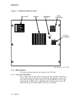
2. Place the battery circuit breaker, located on the front panel of the UPS (see
Figure 3–1), to the OFF position.
3. Place the ac input circuit breaker, located on the front panel of the UPS (see
Figure 3–1), to the OFF position.
4. Place the battery unit circuit breaker, located on the rear panel of the battery
unit (see Figure 3–2), to the OFF position. Access to the battery unit circuit
breaker requires the removal of an access plate located in the lower left rear
of the cabinet.
5. Unplug the system power cord from the electrical outlet.
6. Remove (in one piece) the three rows of EMI panels that are above the bottom
EMI-H panel by using the following steps:
a. Remove the seven 6-32 screws along the top edge of the third EMI panel
row from the bottom.
b. Remove the seven 6-32 screws along the bottom edge of the first EMI
panel row from the bottom.
c. Remove the nine 10-32 screws (three per EMI panel row) down the right
side of the bottom three EMI panel rows.
d. Remove the nine 10-32 screws (three per EMI panel row) down the left
side of the bottom three EMI panel rows.
e. Lift out the bottom three EMI panel rows in one piece.
7. Unplug all load plugs from the distribution receptacles located on the rear
panel of the UPS (see Figure 3–2).
Removal and Replacement 4–1


