16
5.
Input/Output Signal Line Cautions
• All PL Input and Output signal lines must
be separated from all operating circuit
(power) cables.
• If this is not possible, use a shielded cable
and ground the shield.
• To improve noise immunity, it is recommended
to attach a ferrite core to the power cord.
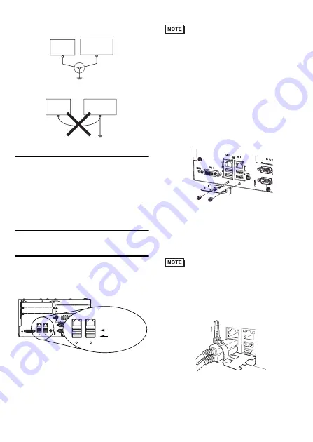
To prevent the USB cable
from coming off
Attaching the USB Cable Clamp
(1) Place the PL unit face-down on a flat sur-
face as shown below. Your PL unit has
four USB connectors.
• When using two or more USB ports, be sure
to first connect one USB cable to the lower
USB connector, and then connect the sec-
ond USB cable to the upper USB connector.
• When using only one of the USB ports, be
sure to use the lower USB connector. This
allows you to securely clamp the USB
cable in the cable clamp.
• The USB cable clamp is not compatible
with the USB connector on the front face.
(2) Fix the USB holder with two screws.
The torque required to tighten these
screws is 0.5 to 0.6 N•m.
(3) As the figure shows, pass the USB Cable
Clamp’s band around the depressed sur-
face of the holder, twist the USB Cable
Clamp’s band around the USB cable, pull
the band in the direction of the arrow, and
then fasten the band using the clamp.
• Be sure the clamp is securely holding the
USB cable’s plug and collar.
• Be sure the clamp is positioned as shown
below, with the clamp pointing upwards - not to
the side. This is to keep the clamp from interfer-
ing with nearby connectors and their cables.
Other
Equipment
Common Grounding (OK)
PL unit
Other
Equipment
Common Grounding
(Not OK)
PL unit
1
2
4
3
USB
LAN1
LAN2
1
2
4
3
USB
LAN1
LAN2
SPK
DV1-I
RESET
Lower USB
Interface
Upper USB
Interface
Summary of Contents for APL3600-TA
Page 18: ...18 ...


