

2
Copyright © 2019 DIGIOP
·
Indianapolis, IN
·
email: [email protected] · tel: 800.968.3606
·
www.digiop.com
DIGIOP is a registered trademark of DIGIOP. All rights reserved.
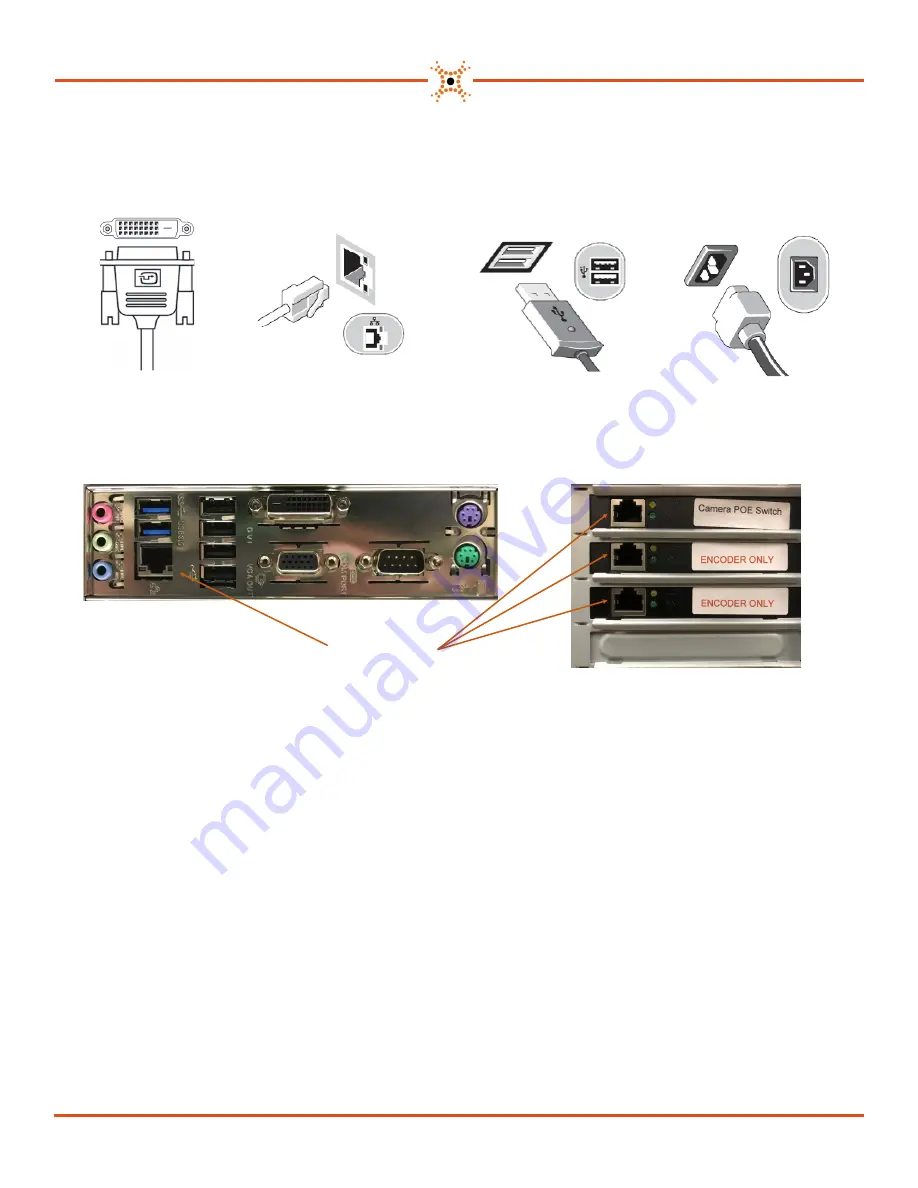
3. Setting Up Your System
1. Connect a monitor(s) to
the VGA and/or DVI-D ports.
2. Connect the network
cable to the Ethernet port on
the Back Panel.
3. Connect the keyboard and
mouse to the USB 2.0 ports.
4. Connect the power cable.
Press the power buttons on
the monitor and computer.
4. Add IP Cameras
5. Add a DIGIOP
®
Encoder (optional add-on)
Back Panel
Expansion Cards
Connect all of your IP cameras to a POE switch. Ensure that the POE switch has adequate power on each port to han-
dle each camera. Connect an Ethernet cable between the POE switch and the Ethernet port on the Expansion Card
labeled
Camera POE Switch.
DIGIOP
®
recommends that you do not connect a cable from your network to the POE
switch. This will keep the IP camera traffic isolated on its own switch.
Connect all of your analog cameras to your DIGIOP
®
Encoder. Connect the provide orange Ethernet patch cable be-
tween the DIGIOP
®
and the Ethernet port on the Expansion Card labeled
Encoder Only
. If you have more than one En-
coder, connect the second Encoder to the second Ethernet port on the Expansion Card labeled
Encoder Only
with the
provided orange Ethernet patch cable. If you have 2
Encoder Only
Ethernet ports, it does not matter in which order you
connect the Encoders.
Ethernet Ports


