background image

19 

       (Menu) 
        Search 
        Timer 
        Record 
        Alarm 
        Remote 
        System 
 

    Event 

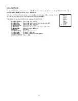
Event Log Viewing 

 
To access the Event Log Viewing option, press 

MENU 

followed by the 4-digit password. Use the 

 / 

 to scroll to the 

Event 

option


and press 

ENTER

 to view the list of logged events

 
Use the 

 / 

 to scroll through the events on the display and 

 / 

 to go to the next page. To view 

the video associated with an event, scroll to the event and press 

ENTER

.  

 
The following is a list of events that can be displayed on the DGR109. 
 

M-HDD WARNING

:    Master HDD might be failed 

M-HDD LOSS:  

Master HDD does not exist.  User can use other HDD. 

M-HDD ERROR:  

Master HDD may contain error. 

S-HDD WARNING:  

Slave HDD may have failed. 

S-HDD LOSS:


Slave HDD does not exist.   User can use other HDD 

S-HDD ERROR:


Slave HDD may contain error. 

HDD FULL:  

HDD is full. 

SYSTEM ERROR:  

System may have failed. 

------02 VLOSS:   

Channel: 2 Video Loss 

------03 ALARM:   

Channel: 3 External I/O Alarm triggered. 

POWER RESTORE

:   Power restore. 

Summary of Contents for DGR109

Page 1: ...9 Channel Digital Video Recorder Models DGR109 Installation User Manual Digimerge Technologies Inc ...

Page 2: ...ironment This equipment generates uses and can radiate radio frequency energy and if not installed and used in accordance with the instruction manual may cause harmful interference to radio communications However there is no guarantee that interference will not occur in a particular installation Operation of this equipment in a residential area is likely to cause harmful interference in which case...

Page 3: ...ecording Setup 13 Timer 13 Record Settings 15 HDD Overwrite Setup 15 Record IPS Setup 15 Record Quality Setup 15 Alarm REC IPS setup 15 Alarm REC Quality setup 15 Motion Trigger Record 15 Camera Channel Setup 16 Motion Detection 17 Event Log Viewing 19 Operation 20 On Screen Display OSD 20 Recording Methods 20 Viewing Options 20 Individual Camera Select 1 4 20 Quad View Select 20 Picture in Pictur...

Page 4: ...turning the power off correctly This equipment should be operated using only the power source from standard package Unauthorized repair or parts substitutions may result in fire electric shock or other hazards Do not switch the Power On Off within short period within 3 seconds Do not attempt to service this equipment by yourself Refer all servicing to qualified service personnel This installation ...

Page 5: ...Audio inputs and 2 outputs Resolution 704X564 full screen 352X282 4 channels 224X188 9 channels Independent main and call monitor outputs allow simultaneous or full screen viewing Multi screen display mode 9 channel alarm input alarm display and 1 alarm output Video loss detection able to record 160 events on each channel Power loss memory feature In case of power failure set up parameter will rem...

Page 6: ...ON to indicate that the DVR is in Standby mode 3 Press the Power button The POWER LED will turn from red to orange and other red LED indicators will turn ON Note the system takes approximately 5 to 15 seconds to power up During the power up you will see the following messages HDD Detecting followed by Master HDD Connected Once connected the POWER LED will change to green and the red indicator ligh...

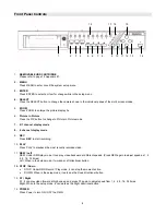
Page 7: ...Press REC to start recording 10 PLAY Press PLAY to playback the most recently recorded video 11 REW Left REW Under DMR play mode it can play video backward at different speeds Press REW again to adjust speed as 1 2 4 8 16 32 times Left When in the setup mode it works as Left directional button 12 STOP Down STOP Under DMR Record Play mode it can stop the moment action DOWN When in the setup mode it...

Page 8: ...ing condition HDD Full HDD is full ALARM If you want to turn off the ALARM LED light please refer to page 13 and set the Camera ALARM item as OFF all of the cameras should be set as OFF TIMER When Timer is set as Enabled PLAY On Play mode REC On Recording mode 17 SLOW Press to slow down the playback speed 18 CAMERA SELECT 1 9 Press the Camera Select 1 9 to select specified camera ...

Page 9: ...ction allows for HI impedance or 75ohms 4 VIDEO INPUT 1 9 Connects to a video source i e camera 5 CALL Connects to the CALL monitor for real time sequencing 6 AUDIO OUTPUTS 1 2 Connects to a speaker or a monitor with audio speaker 7 AUDIO OUTPUTS R L Connects to an audio source for recording purposes i e microphone 8 MONITOR Connects to the main display monitor 9 LOOP Allows connection to other vi...

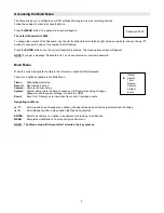
Page 10: ...ssword is entered the main menu options will be displayed There are 5 options available in the Main Menu Timer Scheduling Recording Record Record mode set up Camera Camera channel set up System System Setup Sets the date chooses an HDD overwrite setting changes password resets system settings or clears the HDD Event Event List Allows you to view video from a list of recorded events Navigating the ...

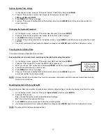
Page 11: ...ENTER 2 Press to enable or disable the internal audible alarm buzzer Options are ON Buzzer is on When the DVR detects an alarm the system sounds the internal buzzer to alert the user OFF Buzzer is off 3 Press MENU to confirm your change 4 Press to move to another field on the System screen or press MENU to exit Setting the External Audible Alarm device To enable or disable the External Audible Ala...

Page 12: ...e 1 On the System screen press to select Dwell Time then press ENTER 2 Press to select the desired time 1 10s 3 Press MENU to confirm your change 4 Press to move to another field on the System screen or press MENU to exit Setting the Message Latch feature This feature determines if the On Screen messages will remain on the screen or disappear after 10s To set the Message Latch 1 On the System scre...

Page 13: ... press to select Clear HDD and then press ENTER 2 Press to choose YES to clear the HDD or NO to leave as is 3 When you choose Yes on this option and press ENTER the DVR will prompt 4 Press to confirm clearing or to cancel 5 Press MENU to confirm your change 6 Press to move to another field on the System screen or press MENU to exit this screen and confirm the current operation NOTE Clearing the da...

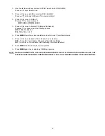
Page 14: ...ream with the control codes shown Please refer to Appendix 3 for information on the Pin connections and command protocols that would be used in this application Timer Recording Setup On the Main menu selecting the Timer option will allow you to set daily schedules in which you would like the DVR to automatically record Pressing ENTER after scrolling to the Timer option will bring up the following ...

Page 15: ... 2 1 PAL 12A 12 6 3 2 1 6 Press MENU to confirm current operation and enter to next Timer Record setup 7 Press move location to Timer Enable Yes or No setup YES To confirm Timer Enable Scheduling Timer Record feature NO To confirm no Timer Enable No Scheduling Timer Record feature 8 Press MENU to exit and confirm current operation 9 Press MENU again to exit and close TIMER setup mode NOTE WHEN THE...

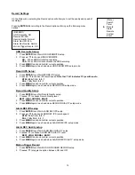
Page 16: ...TER to confirm Record Quality setup 2 Press to choose Record Quality level BEST HIGH NORMAL BASIC 3 Press MENU to exit and confirm current operation 4 Press MENU again to exit and close RECORD QUALITY setup mode Alarm REC IPS setup 1 Press ENTER to confirm ALARM REC IPS setup 2 Press to choose ALARM REC IPS record speed NTSC 15A 15 8 4 2 1 PAL 12A 12 6 3 2 1 3 Press MENU to exit and confirm curren...

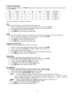
Page 17: ... the screen 3 Press to select 0 9 on the screen 4 Press MENU to confirm and exit the Brightness Contrast or Color control feature 5 Press MENU again to exit the Camera Setup Option Alarm Polarity This feature is used to select the alarm polarity as LOW OFF HIGH 1 Press to select the desired time camera channel 1 9 then press ENTER 2 Press to select the Alarm Polarity feature on the screen 3 Press ...

Page 18: ...time 4 moves the target cursor down one row at a time 5 moves the target cursor left one column at a time 6 moves the target cursor right one column at a time 7 Press ENTER to turn the target cursor ON Press ENTER again to turn the target cursor OFF 8 Camera Select 1 15 toggles the corresponding target on the cursor line ON or OFF see Figure 1 1 There are only 15 targets in a row therefore only Ca...

Page 19: ...ON DETECTION SETUP 1 9 1 2 3 4 5 6 7 8 9 10 11 12 13 14 15 032 Figure 1 2 MOTION DETECTION SETUP LINE 1 2 3 4 5 6 7 8 9 10 11 12 13 14 15 032 Figure 1 3 MOTION DETECTION SETUP ALL 1 2 3 4 5 6 7 8 9 10 11 12 13 14 15 032 ...

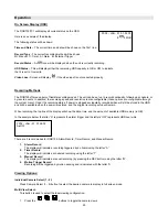
Page 20: ...an event scroll to the event and press ENTER The following is a list of events that can be displayed on the DGR109 M HDD WARNING Master HDD might be failed M HDD LOSS Master HDD does not exist User can use other HDD M HDD ERROR Master HDD may contain error S HDD WARNING Slave HDD may have failed S HDD LOSS Slave HDD does not exist User can use other HDD S HDD ERROR Slave HDD may contain error HDD ...

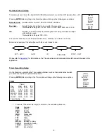
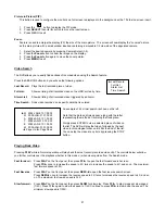
Page 21: ...recorded video will still be stored in the HDD and will be available when the power is restored and the original recording setup will remain When recording the top line of the display will show the date time and the amount of available HDD memory in GB In the example below the letter A represents the alarm trigger and the letters OW represents HDD over write There are 3 record modes for DGR109 Ala...

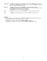
Page 22: ...p The controls below will allow you further controls over the playback whether in this mode or when viewing video from the Search mode Fast forward Press PLAY on the front panel then press FF to open the fast forward search screen Press FF once to increase the speed to 2X twice to increase the speed to 4X and so on The maximum fast forward speed is 32X Fast Reverse Press PLAY on the front panel th...

Page 23: ...esult in forward image by image playback Pressing REW will result in reverse image by image playback Pause Press PLAY on the front panel and then press PAUSE to lock the current image on the screen Stop Press STOP on the front panel whenever you want to return the DVR to live monitoring mode Key Lock For added security you can Lock the buttons on your DGR109 Locking disables the functionality of t...

Page 24: ...eck that Timer Alarm Enable is set to YES Timer Alarm recording isn t working Check if the system is in Key Lock mode Press MENU and ENTER at the same time to escape the Key Lock mode Buttons aren t working when pressed Check the power source cord connections Check that there is power at the outlet No Power Need to insert HDD Make sure that the HDD Cartridge is locked then press any key to continu...

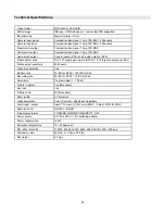
Page 25: ...gets per camera PAL Motion detect sensitivity 256 Levels Video loss detection Yes Refresh rate 72 IPS for NTSC 100 IPS for PAL Recording rate 25 IPS for NTSC 12 IPS for PAL Dwell time Programmable 1 10 Sec Picture in picture Yes Moveable Key lock Yes Picture zoom 2X Moveable Camera title 6 Characters Video adjustable Color Contrast Brightness Adjustable Alarm input output Input TTL input Hi 5V Low...

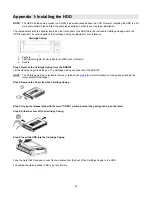
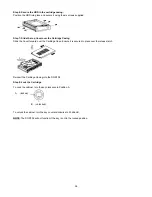
Page 26: ...icator 3 Handle Step 1 Remove the Cartridge Casing from the DGR109 Lift the Handle and pull towards you The Cartridge Casing will slide out of the DGR109 NOTE The Cartridge must be unlocked to remove it please see step 8 for more information on locking and unlocking the removable HDD cartridge Step 2 Remove the Cover from the Cartridge Casing Step 3 Unclip the release latch with the word OPEN prin...

Page 27: ...idge Casing Slide the Cover forward over the Cartridge Case Ensure it is secured in place over the release latch Reinsert the Cartridge Casing into the DGR109 Step 8 Lock the Cartridge To Lock the cabinet turn the key clockwise to Position A To unlock the cabinet turn the key counter clockwise to Position B NOTE The DGR109 will not function if the key is not in the locked position ...

Page 28: ...27 Appendix 2 Connection Diagram to Cameras and Monitor PC RS232 Sensor Alarm Alarm Input Main Monitor Video Camera 9 2 1 Call Monitor Video Output Audio Output Audio Input 4 Channels ...

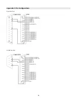
Page 29: ...28 Appendix 3 Pin Configurations 9 pin Com Port 25 Pin Com Port ...

Page 30: ...T 7 Used to connect an alarm sensor between ALARM INPUT 7 PIN 4 and GND PIN 1 to trigger an alarm on Camera 7 which can activate the internal audible alarm and start recording PIN 2 ALARM INPUT 8 Used to connect an alarm sensor between ALARM INPUT 8 PIN 4 and GND PIN 1 to trigger an alarm on Camera 8 which can activate the internal audible alarm and start recording PIN 22 ALARM INPUT 9 Used to con...

Page 31: ...nd brackets for rack mounting applications can be purchased as an optional accessory Front Angle with Rack Mount Side View with Rack Mount For more information about the rack mount other accessories through Digimerge please visit www digimerge com ...

Page 32: ...r 105hr 200hr 400hr 800hr 1600hr HDD Type 80GB IPS 25A 15 8 4 2 1 Best 24hr 48hr 90hr 180hr 360hr 720hr High 30hr 60hr 1136hr 225hr 450hr 900hr Normal 48hr 96hr 1600hr 360hr 720hr 1440hr Record Quality Basic 80hr 160hr 300hr 600hr 1200hr 2400hr HDD Type 120GB NOTE The above data has been taken from actual test data obtained using recordings from a normal TV program and is to be used for reference ...

Page 33: ... 0x31 1 KEY_SELECT 0x73 s KEY_CH2 0x32 2 KEY_ENTER 0x0D ENTER KEY_CH3 0x33 3 KEY_4CUT 0x61 a KEY_CH4 0x34 4 KEY_ZOOM 0x5A Z KEY_CH5 0x35 5 KEY_9CUT 0x62 b KEY_CH6 0x36 6 KEY_PIP 0x70 p KEY_CH7 0x37 7 KEY_16CUT 0x63 c KEY_CH8 0x38 8 KEY_SLOW 0x53 S KEY_CH9 0x39 9 KEY_REC 0x72 r KEY_LEFT 0x4C L KEY_UP 0x55 U KEY_PLAY 0x50 P KEY_DOWN 0x4E N KEY_RIGHT 0x52 R KEY_POWER 0x57 W KEY_KEY_LOCK 0x4B K ACT 0x...

Page 34: ...X 60GB 4W060H4 60GB 5400rpm Maxtor DiamondMax Plus 9 80GB 7200 rpm Maxtor DiamondMax Plus 9 Model 6Y120L 120GB 7200 rpm Maxtor DiamondMax Plus 9 Model 6Y160L0 160GB 7200rpm Seagate Barracuda ATA IV ST380021A 80GB 7200rpm Seagate Barracuda ATA V ST3120023A 120GB 7200 rpm Seagate Barracuda 7200 7 Plus ST3160023A 160GB 7200 rpm Western Digital Caviar WD1200BB 00CAA1 120GB 7200rpm Western Digital Cavi...

Page 35: ...ROVIDED UNDER THIS LIMITED WARRANTY IS THE EXCLUSIVE REMEDY OF THE PURCHASER DIGIMERGE SHALL IN NO EVENT BE LIABLE FOR ANY SPECIAL INDIRECT INCIDENTAL PUNITIVE OR CONSEQUENTIAL DAMAGES OF ANY KIND OR CHARACTER INCLUDING WITHOUT LIMITATION PERSONAL INJURY LOSS OF REVENUE OR PROFITS FAILURE TO REALIZE SAVINGS OR OTHER BENEFITS OR CLAIMS AGAINST THE PURCHASER BY ANY THIRD PERSON EVEN IF DIGIMERGE HAS...

Page 36: ...35 Digimerge Technologies Inc 300 Alden Road Markham Ontario L3R 4C1 www digimerge com rev04 ...

Reviews: