background image

12/21/2018

chipKIT DP32 Reference Manual [Reference.Digilentinc]

https://reference.digilentinc.com/chipkit_dp32/refmanual

7/17

In addition to being compatible with the MPIDE, the DP32 board can be used as a more traditional microcontroller development board
using Microchip Development Tools.

The unloaded connector JP6 on the right side of the board is used to connect to a Microchip development tool, such as the PICkit3™ or
the Digilent chipKIT PGM. The holes for JP6 are staggered so that a standard 100-mil spaced 6-pin header can be press fit to the board
without the need to solder it in place. Any Microchip development tool that supports the PIC32MX2xx microcontroller family and can
be used provided it uses the same 6-pin interface as the PICkit3.

The Microchip MPLAB® IDE or the MPLAB® X IDE can be used to program and debug code running on the DP32 board. These
tools can be downloaded from the Microchip website.

Using the Microchip development tools to program the DP32 board will cause the boot loader to be erased. To use the board with the
MPIDE again, it is necessary to program the boot loader back onto the board. The boot loader image can be downloaded here

(https://reference.digilentinc.com/_media/chipkit_dp32/chipkit_bootloader_dp32.zip)

 from the DP32 product page on the Digilent website. To

reload the boot loader, you will need to have MPLAB X and a licensed Microchip debugger/programmer, such as a PICkit®3 or
chipKIT PGM programmer, and then perform the following steps.

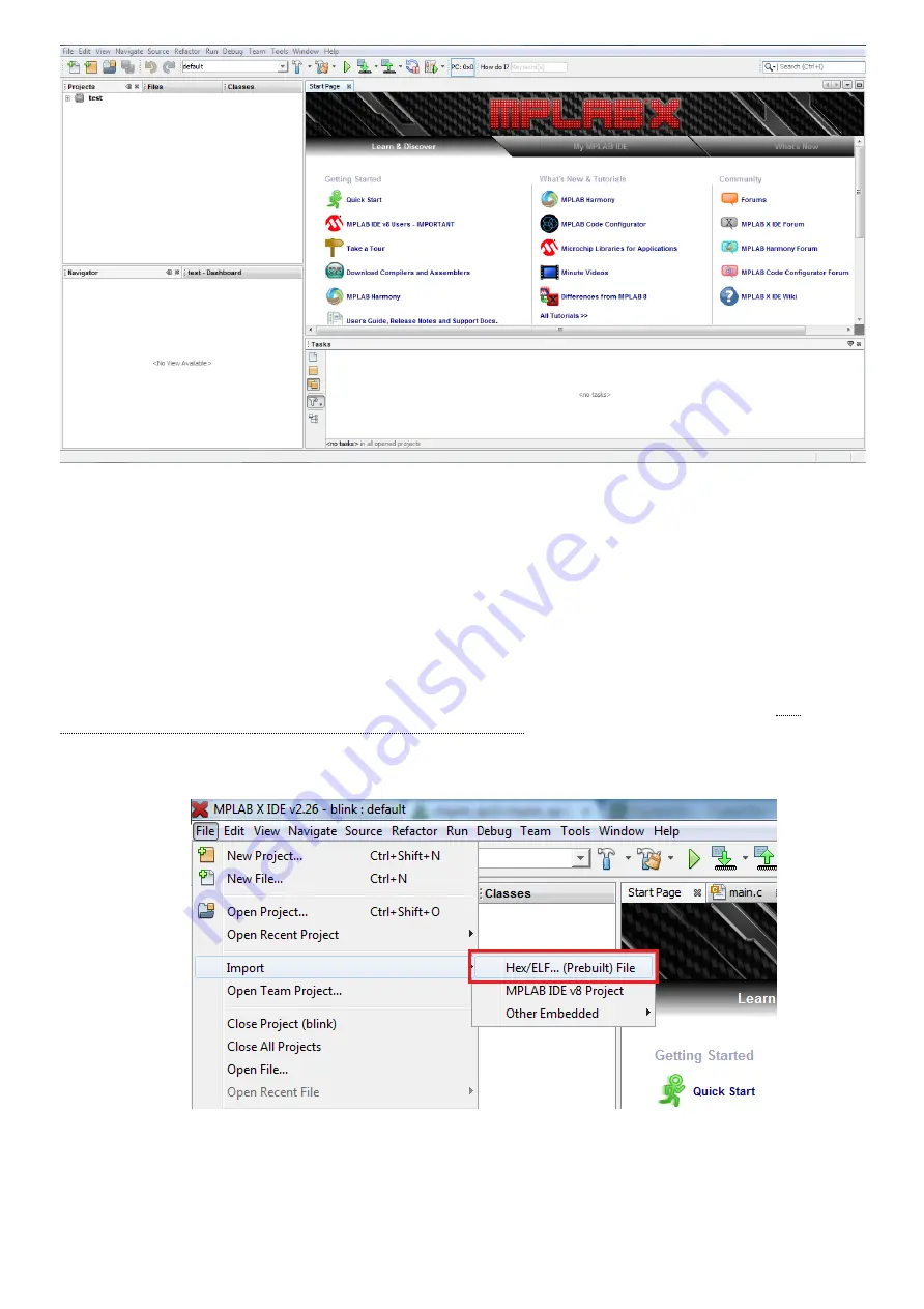
1. Open MPLAB X. On the top task bar, click on “File”, highlight “Import”, and click on “HEX/ELF Prebuilt File”

2. Click on “Browse” and search for the chipKIT-DP32.HEX file you downloaded from the webpage. (If you have more than one

board from the chipKIT family, it may be helpful to store all of your applicable boot loaders in one common file.)

3. Select “32-bit MCUs (PIC32)” in the “Family:” dialog box.
4. Select the device ID “PIC32MX250F128B” in the “Device:” dialog box.
5. Make sure your programmer device is connected and selected in the “Hardware Tool” box at the bottom. The chipKIT PGM was

used for this example. Click “Next” when the correct options have all been chosen.

3.3 Reloading the MPIDE Boot Loader

Summary of Contents for chipKIT DP32

Page 1: ...PIC32MX250F128B microcontroller This microcontroller features a 32 bit MIPS processor core running at 40 MHz 128K of flash program memory and 32K of SRAM data memory It is suitable for building projects directly on the board utilizing the provided prototyping area but it can also be used as a device programmer to program the microcontrollers for inclusion in custom built projects The DP32 can be p...

Page 2: ...ils If these peripherals are needed in the design then the microcontroller can be reconfigured to allow these pins to be used for other purposes Nine of the digital I O pins are shared with the analog inputs and can be used as analog input pins The PIC32MX250F128B microcontroller supports peripheral functions such as UART SPI and I C as well as pulse modulated outputs To use the peripheral functio...

Page 3: ...ed for USB operations JP2 and JP3 D and D USB Signals These jumpers are shipped unloaded The trace between the two terminals may be cut if USB functionality is required to be permanently disabled Once the traces have been cut it is possible to solder jumper pins in these locations to re enable the D and D signals as desired 3 J2 USB Connector for USB Serial Converter This connects to a USB port on...

Page 4: ... to Rev B see images Be sure you know which Rev you have The square solder pad should connect to pin 1 on the debugger Attaching the debugger incorrectly will almost certainly fry either the DP32 the debugger or both Please refer to the section titled Programming the DP32 of this manual for more information on using a debugger 12 Reset Button When pressed the microcontroller resets the currently l...

Page 5: ... folder in the MPIDE distribution In order to install the driver on a Windows based machine follow the steps below You should not need to manually install the drivers on a machine with a non Windows OS 1 Open MPIDE to ensure that it works Close it and make sure that your DP32 is unplugged from the computer 2 Navigate to the MPIDE installation folder The file path should be something like C Program...

Page 6: ...sketch loaded on the board and you cycle power to the board it will automatically reenter sketch mode Each time you edit your sketch and need to reload it to the board you will need to exit sketch mode by pressing and holding BTN PGM pressing RESET and then releasing both to re enter program mode Since the board resets between program mode and sketch mode the serial port will disconnect and then r...

Page 7: ...ill cause the boot loader to be erased To use the board with the MPIDE again it is necessary to program the boot loader back onto the board The boot loader image can be downloaded here https reference digilentinc com _media chipkit_dp32 chipkit_bootloader_dp32 zip from the DP32 product page on the Digilent website To reload the boot loader you will need to have MPLAB X and a licensed Microchip deb...

Page 8: ...it in whichever file you wish Default names will be auto populated 7 Check the box labeled Set as main project then click Finish 8 The project may not default to the main project even if you selected it before If it is not in bold in the project list on the left right click on the boot loader project scroll down to and click on Set As Main Project This should change the typeface to bold ...

Page 9: ... into stand alone projects Additional ICs can then be acquired through Microchip directly Simply go to www microchipdirect com https www microchipdirect com and search for MX250F128B As of this writing there are two options for the IC in the DIP footprint one that comes pre loaded with the chipKIT boot loader and one that does not Once you have your new ICs the original IC can be carefully removed...

Page 10: ... at a time The DP32 has a single voltage regulator mounted on the underside which regulates either 5V from USB to 3 3V or a maximum of 15V external voltage to 3 3V The 3 3V regulator is a Microchip MCP1703 This regulator is rated for a maximum output current of 250mA This regulator has internal short circuit protection and thermal protection It will get noticeably warm when the current consumed by...

Page 11: ...erial Clock and Master In Slave Out lines respectively In addition to the digital I O there are Analog inputs available on the board called A0 through A8 These pins are shared on digital pins 6 thru 14 I C Synchronous serial interface The I C1 interface is available on pins 2 and 3 When using the I C interface it is necessary to set JP4 and JP5 such that pullups are present on the bus This is done...

Page 12: ...implemented as Pin 14 SS Pin 2 MOSI Pin 13 MISO and Pin 8 SCK This pin map does not define the full functionality for every pin For a complete reference of pin functionality please see the PIC32250F128B datasheet available from Microchip http ww1 microchip com downloads en DeviceDoc 60001168F pdf http ww1 microchip com downloads en DeviceDoc 60001168F pdf When using TimerSerial UART ports with MPI...

Page 13: ...MD0 LD4 12 A6 5 RB1 PGEC1 AN3 C1INC C2INA RPB1 CTED12 PMD1 LD3 13 A7 6 RB2 AN4 C1INB C2IND RPB2 SDA2 CTED13 PMD2 LD2 14 A8 7 RB3 AN5 C1INA C2INC RTCC RPB3 SCL2 PMWR LD1 15 9 RA2 OSC1 CLKI RPA2 8 MHz Clock In 16 10 RA3 OSC2 CLKO RPA3 PMA0 8 MHz Clock Out 17 11 RB4 SOSCI RPB4 BTN2 PGM 18 12 RA4 SOSCO RPA4 T1CK CTED9 PMA1 IC4 Serial In 1 nMCLR 8 GND 13 VDD 15 VBUS 19 GND 20 VCAP 23 VUSB3V3 27 AVSS N ...

Page 14: ... 10 A4 RA1 PGEC3 VREF CVREF AN1 RPA1 CTED2 PMD6 RA1 IC4 Serial Out 4 11 A5 RB0 PGED1 AN2 C1IND C2INB C3IND RPB0 PMD0 RB0 LD4 5 12 A6 RB1 PGEC1 AND3 C1INC C2INA RPB1 CTED12 PMD1 RB1 LD3 6 13 A7 RB2 AN4 C1INB C2IND RPB2 SDA2 CTED13 PMD2 RB2 LD2 7 14 A8 RB3 AN5 C1INA C2INC RTCC RPB3 SCL2 PMWR RB3 LD1 8 GND VSS 9 15 RA2 OSC1 CLKI RPA2 RA2 8 MHz Clock In 10 16 RA3 OSC2 CLKO RPA3 PMA0 RA3 8 MHz Clock Ou...

Page 15: ...2 chipkit_dp32_sch pdf from the DP32 product page on the Digilent website Appendix D Schematic First Name Last Name Email Address Submit Subscribe to our Newsletter Xilinx University Program https store digilentinc com partners xilinx university program Technology Partners https store digilentinc com technology partners Distributors https store digilentinc com our Our Partners Technical Support Fo...

Page 16: ...store digilentinc com Internships https store digilentinc com https twitter com digilentinc https www facebook com Digilent https www youtube com user DigilentInc https instagram com digilentinc https github com digilent https www reddit com r digilent https www linkedin com company 1454013 https www flickr com photos 127815101 N07 Connect With Us ...

Page 17: ...12 21 2018 chipKIT DP32 Reference Manual Reference Digilentinc https reference digilentinc com chipkit_dp32 refmanual 17 17 ...

Reviews: