background image

SM-500V2 Service Manual Edition 5 


108

Items


Y  N 

Identification 

Removal 

procedure 

Comments 

Rear Display Assembly


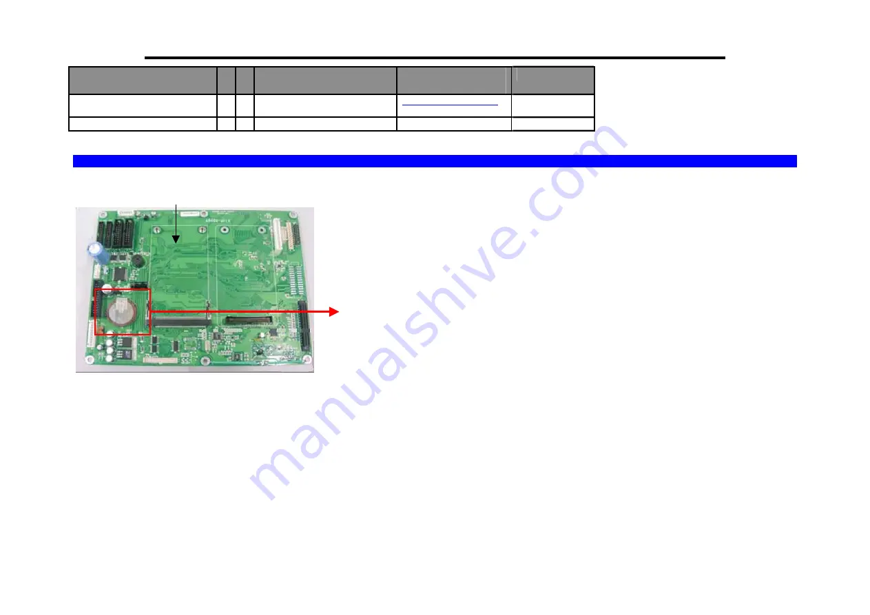
12.2   Location of Battery in Main-board  


MAIN BD BLK AG (SM-720) 
44011690100700 

Lithium Battery
(BT1) 

Summary of Contents for SM-720

Page 1: ...COPYRIGHT 2006 TERAOKA WEIGH SYSTEM PTE LTD SERVICE MANUAL DIGITAL COMPUTING PRINTING SCALE SM 720 Edition 5 ...

Page 2: ...Elevated Type 19 4 1 1 Scale Assembly 19 4 1 1 1 Display Pole Kit Mounting 19 4 1 1 2 Level Adjustment 19 4 1 2 Default Country Spec Setting 19 4 1 3 Calibration 23 4 1 4 User Spec Setup Procedure 24 4 1 5 Weigh Measurement Spec Setup Procedure 26 4 2 Touch Pole Touch Bench and Touch Elevated Type 28 4 2 1 Default Country Spec Setting 28 4 2 2 Calibration 29 4 2 3 User Spec Setup Procedure 30 4 2 ...

Page 3: ...Procedure of Linerless Machine Conversion 50 6 7 Method of Assembly Sealing Screw Sticker 52 6 7 1 For All Machine except Console Type 52 6 7 2 For Hanging Type 53 6 7 3 For Console Type 54 7 EXPLODED VIEW 55 7 1 Pole Type 55 7 2 Bench Type 56 7 3 Hanging Type 57 8 DISASSEMBLY 58 8 1 Pole Type Disassembly 58 8 2 Pole and Bench AD Board Disassembly 61 8 3 Pole and Bench Load cell Disassembly 62 8 4...

Page 4: ...e 99 12 TREATMENT AND RECOVERY OF WEEE 104 12 1 Component listing of Hazardous Material 104 12 2 Location of Battery in Main board 108 13 BLOCK DIAGRAM 109 13 1 SM 720EB SM500 LCD Option 109 13 2 SM 720DP SM800 LCD Option 110 13 3 SM 720DP SM500 LCD Option 111 13 4 SM 720EV SM800 LCD Option 112 13 5 SM 720EV SM500 LCD Option 113 13 6 SM 720TEB SM500 LCD Option 114 13 7 SM 720TEB SM800 LCD Option 1...

Page 5: ...ny errors or damages arising from misinterpretation of any procedure Screen displays operating procedures and supporting features might vary with different software version releases This document shall not be reproduced whether in part or whole without the written consent from Teraoka Weigh System Pte Ltd Teraoka Weigh System Pte Ltd 4 Leng Kee Road 06 01 SIS Building Singapore 159088 ...

Page 6: ...IONS FOR PLUGGABLE EQUIPMENT THAT THE SOCKET OUTLET SHALL BE INSTALLED NEAR THE EQUIPMENT AND SHALL BE EASILY ACCESSIBLE POUR LE MATÉRIEL RACCORDÉ PAR PRISE DE COURANT LE SOCLE DE PRISE DE COURANT DOIT ÊTRE INSALLÉ À PROXIMITÉ DU MATÉRIEL ET DOIT ÊTRE AISÉMENT ACCESSIBLE FOR CONTINUED PROTECTION AGAINST RISK OF FIRE REPLACE ONLY WITH SAME TYPE AND RATING OF FUSE POUR NE PAS COMPROMETTRE LA PROTECT...

Page 7: ...of the following measures Reorient or relocate the receiving antenna Increase the separation between the equipment and receiver Connect the equipment into an outlet on a circuit different from that to which the receiver is connected Consult the dealer or an experienced radio TV technician for help This device complies with Part 15 of the FCC Rules Operation is subject to the following two conditio...

Page 8: ...x 230 W x 855 H Self Service SM 720 BS 497 L x 482 W x 779 H Display 3 Color LCD with Backlight 64 x 264 dots DP EV H BS Type 24 x 264 dots B Type Display Angle 50 and 80 degree Key Mechanical Switch Color Blue Grey Metalic Silver Number Of Preset Key SM 720EB 32 SM 720DP 56 100 SM 720EV 56 100 SM 720H 56 SM 720BS 48 60 96 120 Capacity 6kg less than 3kg e 1g more than 3kg e 2g 15kg less than 6kg e...

Page 9: ...lean scale only with a damp cloth 1 3 Type of Interface Standard RS 232C FL 1 PC connection PS2 Keyboard Cash drawer 3 Pin Din for TWB 01750 Cash drawer RJ11 type connector for TWB 01750 1 onwards RS 485 PC connection Optional Ethernet Client Server TCP IP protocol Character Generator Interface with PC can either use RS 232C RS 485 or Ethernet 1 4 Main Components 1 XYLINX XC95144XL 10TQG144C M B U...

Page 10: ...CPU BD U7 U8 It s a high performance very low power CMOS static Random Access Memory organized as 524 288 words by 16 bits and operates from a wide range of 2 4V to 5 5V supply voltage 6 AM29LV320DB90EI CPU BD U9 It s a 32 megabit 3 0 volt only flash memory device and is designed to be programmed in system with the standard 3 0 volt Vcc supply and can also be programmed in standard EPROM programme...

Page 11: ...SM720 Service Manual Edition 5 9 2 OVERVIEW 2 1Dimension in mm 2 1 1 SM 720 DP 2 1 2 SM 720 EB ...

Page 12: ...SM720 Service Manual Edition 5 10 2 1 3 SM 720 EV 2 1 4 SM 720 TDP ...

Page 13: ...SM720 Service Manual Edition 5 11 2 1 5 SM 720 TEB 2 1 6 SM 720 TEV ...

Page 14: ...SM720 Service Manual Edition 5 12 2 1 7 SM 720 H Note This dimension is using 72mm Printer 2 1 7 SM 720 BS ...

Page 15: ...SM720 Service Manual Edition 5 13 2 2Key sheet Layout 32 Preset Keys 56 Preset Keys 100 Preset Keys ...

Page 16: ...alue Select NO in S and Z Mode Item Test print in S Mode CLEAR KEY Clear numeric values Select YES in S and Z Mode RE ZERO KEY Reset weight to zero PRE PACK KEY Switch Manual mode and Pre pack mode alternatively The mode status will be indicated in the P and M indicator P PRE PACK MODE M MANUAL MODE Symbol Key Panel Standard Key Panel ...

Page 17: ...D KEY Correct the Sales Data PLU KEY or Call up PLU data Store the programmed data in S mode FEED KEY or Feed Label or Receipt PRINT KEY or Print out Label or Receipt MODE SELECT KEY Five Modes can be selected using this key Indicator R REGISTRATION MODE All the sales transactions are performed Indicator X CHECK MODE Printing out and sales report Indicator S PROGRAM MODE Programming preset data su...

Page 18: ...ge the entry to Left Code type entered Insert Data Switch Cap Lower case Change Font size Delete the Data 2 3Panel Layout Economic Bench and Pole Type For Small LCD Dual Pole Type For Large LCD There are fifteen different indicators on Display Panel as shown below 1 Î0Í Lights when scale is stable at the zero point 2 NET Lights when tare subtraction in performed 3 P Lights when PRE PACK Mode is se...

Page 19: ...ON Mode is selected 9 X Lights when CHECK Mode is selected 10 S Light when PROGRAM Mode is selected 11 Z Lights when TOTAL Mode is selected 12 A Lights when Sales Data is in Memory for CLERK 9995 13 B Lights when Sales Data is in Memory for CLERK 9996 14 C Lights when Sales Data is in Memory for CLERK 9997 15 D Lights when Sales Data is in Memory for CLERK 9998 ...

Page 20: ... screw M4X6 then open the Bottom Cover 3 Loosen the 2pcs Truss Head screw M4X6 and disconnect the Interface Board cable 4 Loosen the 2pcs SEMS B screw M3X6 then open the Insulator 5 Change SW2 jumper to Enable Disable Span Switch 3 2 Span Switch located in Main Board Bottom Cover Interface Board Cable Span Switch SW2 Mainboard Insulator Insulator ...

Page 21: ...lease turn on the span switch before proceed this process Key to press Operation Switch On the Power Show current country SPEC then default Customer Specification setting Follow the instruction a Press the Clear then b Press the Print process to next step CURRENT COUNTRY SPECIFICATION PRESS CLEAR KEY THEN PRESS PRINT KEY 1 Place the display Pole inside the pole bottom base AB 2 Align the four hole...

Page 22: ...ey to press Operation After Reading Country Spec the display will prompt MEMORY CLEAR message MEMORY CLEAR YES NO SELECT SCALE TYPE ENTER SCALE TYPE NUMBER AND PRESS PRINT KEY Scale Type 0 Pole 6 Kg 1 Pole 15 Kg 2 Pole 30 Kg 3 Pole 30 Lb 4 Bench 6 Kg 5 Bench 15 Kg 6 Bench 30 Kg 7 Bench 30 Lb 8 Printer BP 80 90 0 POLE 6 Kg SELECT LABEL LENGTH ENTER LABEL LENGTH NUMBER PRESS PRINT KEY Label Length 0...

Page 23: ...en default Customer Specification setting Follow the instruction a Press the Clear then b Press the Print process to next step CURRENT COUNTRY SPECIFICATION PRESS CLEAR KEY THEN PRESS PRINT KEY KEY TO PRESS OPERATION 0 To 8 Select scale type OR Select scale type Then To set the scale type 54 WG SELECT SCALE TYPE ENTER SCALE TYPE NUMBER AND PRESS PRINT KEY Scale Type 0 Pole 6 Kg 1 Pole 15 Kg 2 Pole...

Page 24: ...n After Reading Country Spec the display will prompt MEMORY CLEAR message MEMORY CLEAR YES NO Key to press Operation If Yes Process of initialize Then go to segment check PLEASE WAIT Key to press Operation If No Go to segment check SM720 VER 29 XXX SELECT LABEL LENGTH ENTER LABEL LENGTH NUMBER PRESS PRINT KEY Label Length 0 Short ÆLabel length up to maximum 120mm 1 Long ÆLabel length up to maximum...

Page 25: ...RATION To calibrate zero point Ensure no weight in platter Wait until the SET WEIGHT PRT shows REMOVE ALL WT PRT KEY TO PRESS OPERATION Place the capacity weight on the scale after the following screen appears Place the capacity weight according to the scale on the platter E g for a 6 Kg scale put a 6 Kg capacity weight on the platter SET WEIGHT PRT KEY TO PRESS OPERATION Press key exit Calibratio...

Page 26: ...tion Mode To change the selection for the Spec press the Number of the selection Press the key to Save go to next Spec Press key to go back to previous Spec Press PLU to save and exit Press Tare to exit without saving KEY TO PRESS OPERATION 0 To 2 0 Select data Refers to Customer Spec setting OR To choose scale type Then To set Save data and increase SPEC No Z MODE PRINT KEY SP0 SELECTION OF ITEM ...

Page 27: ...evious SPEC number KEY TO PRESS OPERATION 1 0 To jump to desire SPEC number KEY TO PRESS OPERATION OR Save SPEC setting and Exit to R mode Do not save SPEC setting and Exit to R mode SP2 RIGHT SIDE PRICE DATA OF ITEM BARCODE 0 BEFORE TAX 1 AFTER TAX SP2 RIGHT SIDE PRICE DATA OF ITEM BARCODE 1 PRICE 2 WEIGHT 3 USER PROGRAMMABLE SP10 FLAG DATA F0 F1 F2 FOR TOTAL BARCODE RANGE 0 999 020 0 000 0 000 0...

Page 28: ...to Weight and Measure Specification Mode To change the selection for the Spec press the Number of the selection Press PRINT key to Save go to next Spec Pres key to go back to previous Spec Press PLU to save and exit Press Tare to exit without saving KEY TO PRESS OPERATION 0 To 1 OR Then Select data Refer to Weight Measurement Spec setting To choose scale type To set Save data and increase SPEC No ...

Page 29: ...Y TO PRESS OPERATION 6 1 0 To jump to desire SPEC number KEY TO PRESS OPERATION OR Save SPEC setting and Exit to R mode Do not save SPEC setting and Exit to R mode Remarks Please restart the scale every time after changing the SPEC SP602 DISPLAY TYPE 0 SINGLE DISPLAY ROW 1 THREE DISPLAY SP601 AUTO ZERO FUNCTION 0 NO AUTO ZERO 1 AUTO ZERO SP610 UNIT PRICE DECIMAL POINT RIGHT SHIFT 0 NO RIGHT 1 RIGH...

Page 30: ...ting Procedure Picture 1 Touch and hold the Corner Side of touch screen panel then switch power ON the scale Note Ensure Span Switch is set in On position 2 Select Countries of scale and touch Save 3 Waiting until display shown Memory Clear and then touch Yes to clear memory Note If press No is not clear the memory ...

Page 31: ... Note Ensure Span Switch is set to Enable 2 In Weight Calibration mode remove all weight from platter and then touch Start 3 Waiting until the display as show and then put Weight full capacity ex 15kg to scale and touch Start 4 In Operation mode touch Registration to ensure the calibration had success completed Note Ensure Set Span Switch is Disable ...

Page 32: ... SPEC if there is some SPEC need to alter Procedure Picture 1 In Operation Menu mode touch User Setup icon 2 Touch Yes 3 The Spec Setup screen will display and touch the Square icon to go to spec setting 4 2 4 IP Address Setting Procedure Picture 1 In Operation Menu mode touch User Setup 2 Touch Yes ...

Page 33: ... 4 In Communication Specs mode touch Client Server Setting 5 In Client Server Setting mode touch the IP Address 6 Set the IP Address and then touch Exit to go to Spec Setting Menu Example 192 168 0 15 7 In Spec Setting menu touch SAVE to save change setting ...

Page 34: ... Read and Write Test KEY TO PRESS OPERATION 0 0 1 Go to Hardware Testing Mode and first it will show the RAM TEST Result HARDWARE TESTING RAM READ WRITE Testing In Progress KEY TO PRESS OPERATION If the RAM is Ok It will show the message below HARDWARE TESTING RAM READ WRITE 1 MB RAM OKAY OR If the RAM is Fail It will show the message below HARDWARE TESTING RAM READ WRITE TEST FAIL PLEASE CHECK YO...

Page 35: ...SE CHECK YOUR HARDWARE 5 1 1 3 ROM Checksum Test KEY TO PRESS OPERATION Testing the ROM Checksum Press the PRINT Key to start the testing HARDWARE TESTING TESTING IN PROGRESS After that HARDWARE TESTING 30B181 TESTING IN PROGRESS 5 1 1 4 PLU Generator Test KEY TO PRESS OPERATION Testing the PLU Generator Press the PRINT key to start PLU Generator HARDWARE TESTING PLU GENARATED OVERWRITE EXITING DA...

Page 36: ...SS Remarks 5 1 1 5 Internal Count KEY TO PRESS OPERATION In the Weighing Mode press Go to Z mode Then turn on the Span Switch TO CLEAR DAILY TRANSACTION PRESS KEY TO PRESS OPERATION 0 0 9 Internal Count Mode Press Tare key to exit IR X XXXXX Z MODE PRINT KEY 5 4 1 6 TEST JIG CONNECTOR for SIO Port Connect pin 4 and pin 5 TEST JIG CONNECTOR for 4 LINE RS485 Port Connect pin 1 and pin 3 Connect pin ...

Page 37: ...1 2 1 Location of Gap Sensor And Peel Sensor 5 1 2 2 Label Gap Sensor Z MODE PRINT KEY The label sensor is to detect the gap between the labels so as to identify the starting position of the label If the gap is not detected properly the scale will issue two or more labels Also different material of label and back paper will have different sensitivity level the variable resistor beside the label se...

Page 38: ...R mode KEY TO PRESS OPERATION 5 1 5 Go to the Peel sensor adjustment KEY TO PRESS OPERATION OR Enter a value for sensor voltage then press OR Once the key is press it will auto set the voltage value and Exit to R mode You can enter the value of the peel sensor voltage then press the PLU key to save and Exit to R mode Exit to R mode without doing anything 0 000 0 000 0 00 0 00 SET PEEL SENSOR VOLTA...

Page 39: ...s only allows adjusting vertical position only KEY TO PRESS OPERATION At R mode KEY TO PRESS OPERATION 5 1 4 Go to Thermal Head calibration THERMAL HEAD CALIBRATION KEY TO PRESS OPERATION 2 0 OR 2 0 OR Adjust upward Adjust downward Store new value and Exit to R mode 0 000 0 000 0 00 0 00 OLD SETTING 0 NEW SETTING 0 0 000 0 000 0 00 0 00 ...

Page 40: ...2 1 Hardware Testing 5 2 1 1 Memory RAM Test Procedure Picture 1 In Operation Menu mode press and hold Re zero and press 0 8 9 3 to go to Maintenance Screen 2 Touch Self Diagnostic to go to self diagnostic mode 3 Touch RAM 4 Waiting until the Testing in Progress 5 Tested OK message will show ...

Page 41: ... Procedure Picture 1 In Operation Menu mode press and hold Rezero and press 0 8 9 3 to go to Maintenance Screen 2 Touch Self Diagnostic to go to self diagnostic mode 3 Touch RS232 4 Ensure the testing result is successful 5 4 TEST JIG CONNECTOR for SIO Port Connect pin 4 and pin 5 Test Ok Test Fail ...

Page 42: ... In Operation Menu mode press and hold Re zero and press 0 8 9 3 to go to Maintenance Screen 2 Touch Self Diagnostic to go to self diagnostic mode 3 Touch 4L MULTI DROP 4 Ensure the testing result is successful 1 6 TEST JIG CONNECTOR for 4 LINE RS485 Port Connect pin 1 and pin 3 Connect pin 2 and pin 4 Test Ok Test Fail ...

Page 43: ...ce Manual Edition 5 41 5 2 1 4 Internal Count Procedure Picture 1 In Operation Menu mode press and hold Re zero and press 0 0 9 to go to Internal Count Mode Note Ensure Span Switch is Enable 2 Internal Count mode ...

Page 44: ...to go to Maintenance Screen 2 Touch Self Diagnostic to go to self diagnostic mode 3 In Self Diagnostic mode press arrow key to scroll down menu then press Printer Sensor 4 Press Print key to Auto Detect peel sensor setting and touch panel will go back to Self Diagnostic menu After finish test label printing and ensure the sensor will be detect properly for label ...

Page 45: ... mode press and hold Re zero and press 0 8 9 3 to go to Maintenance Screen 2 Touch Self Diagnostic to go to self diagnostic mode 3 In Self Diagnostic mode press arrow key to scroll down menu and then press Gap Sensor 4 The screen will show the value of gap sensor 5 Take out the Cassette from printer ...

Page 46: ...ter and then press Feed key to Auto Detect Setting and press PLU key After finish testing the label printing 5 2 2 3 Label Printing Layout Setting Procedure Picture 1 In Operation Menu mode touch Feed Setting 2 Touch Feed Setting and set adjust new value of Feed Setting Note Reduction Value From OLD VALUE will make the printing on the label will go to Bottom side Additional Value From OLD VALUE wi...

Page 47: ...ng Procedure Picture 1 In Operation Menu mode touch Program to go to Programming Mode 2 In Programming Mode touch Date Time 3 Press Number key button and then touch the inside box line of Date Time to insert number After completed touch Save button to save change ...

Page 48: ...int head is required Please use the cleaning kit supplied with the product Instruction 1 Turn OFF Scale by Main Power Switch 2 Open the Printer Side Door first after that press on the top of Printer Front Door and pull out the cover toward in front 3 Push the Printer Head Handle to up for Printer Head in upper position Printer Front Door Printer Side Door Printer Head Handle Printer Head ...

Page 49: ...thing sticking on thermal head with sharp objects this will DAMAGE the thermal print head 5 After Finish cleaning press down the Printer Head Handle first then close the Printer Front Door and Printer Side Door 6 Turn ON the scale and depress FEED key to feed the label 6 2 Basic Maintenance Clean scale surfaces and platter periodically with a soft damp cloth Do not use alcohol or detergent Cleanin...

Page 50: ...Printer Head Handle to up for Printer Head in upper position 4 Need to take out the Thermal Head wire 5 Use the Hand push the Thermal Head to up first then pull out the thermal head Because the thermal head bracket catch by printer head bracket 6 Unscrew the 2pcs Sems B M3X6 screw to take out Thermal Head or adjustment the alignments Printer Side Door Printer Head Handle Printer Front Door SM720 ...

Page 51: ...LCD JP4 JP5 800LCD Short 1 2 Short 1 2 TYPE 4 Both LCD Operator and Customer are using 300LCD then follow the below table Type of LCD JP4 JP5 300LCD Short 2 3 Short 1 2 6 5 Shift between New and Old Type Customer Display LCD to Activated SM 720 have to provide New and Old type hardware of Display LCD the below method is for scale machine to activated and shift between of the two type Display LCD N...

Page 52: ...SM720 Service Manual Edition 5 50 6 6 Procedure of Linerless Machine Conversion 1 2 3 ...

Page 53: ...SM720 Service Manual Edition 5 51 4 5 6 ...

Page 54: ...SM720 Service Manual Edition 5 52 6 7 Method of Assembly Sealing Screw Sticker 6 7 1 For All Machine except Console Type SM 720 SEALING METHOD ALL VARIANT MODELS ...

Page 55: ...SM720 Service Manual Edition 5 53 6 7 2 For Hanging Type SM 720 HANGING SEALING METHOD ...

Page 56: ...SM720 Service Manual Edition 5 54 6 7 3 For Console Type SM 720 WITH EXTERNAL LOADCELL SEALING METHOD ALL VARIANT MODELS ...

Page 57: ...ASSY AA PLATER SUPPORT PLATTER SUPPORT ASSY TOP COVER KEYBOARD ASSY SWITCHING PS TZD200 JA ELEC BLK SM500V2 AC PWR BRACKET AB FRONT COVER MAINBOARD PRINTER KIT CASSETTE KIT PRINTER DOOR COVER ETHERNET ASSY LOADCELL NMB C2G1 30K S23 ELEC BLK SM300 A D 1 POLE DISPLAY ASSY BRACKET DQ NEW DIECAST MB COV BRACKET BZ M B SEAL ...

Page 58: ...RD ASSY SWITCHING PS TZD200 JA ELEC BLK SM500V2 AC PWR BRACKET AB FRONT COVER MAINBOARD PRINTER KIT CASSETTE KIT PRINTER DOOR COVER ETHERNET ASSY LOADCELL NMB C2G1 30K S23 ELEC BLK SM300 A D 1 DISPLAY ASSY BRACKET DQ NEW DIECAST MB COV BRACKET BZ M B SEAL FRONT DOOR ASSY SUPPORT AA LC DIECAST TOP 1 2 3 1 4 5 6 ...

Page 59: ...DOME REAR COVER ASSY ELEC ASSY SM500V2 M B SWITCH ASSY DC FAN AD0424H8 70 ELEC BLK SM300 A D 1 BRACKET AK LOAD SUPPORT BRACKET AG FRAME PRT WALL BRACKET AZ TUNNEL BRACKET BA SM500H M B PRINTER COVER ASSY BRACKET AM COL MAIN COVER H SIDE ASSY BRACKET AJ FAN BRACKET BD SM500H POWER BRACKET AE FRAME TOP BRACKET AF LOAD CENTER ELEC BLK SM500H CLCD PWR EC AXIS ASSY LOADCELL ASSY FRONT COVER ASSY PAN AC...

Page 60: ...anual Edition 5 58 8 DISASSEMBLY 8 1 Pole Type Disassembly 101 101 101 101 102 102 102 102 104 104 103 103 103 Screw Type 101 Flat Head M4X16 4pcs 102 Sems B M4X10 4pcs 103 Flat Head M3X5 3pcs 104 Truss Head M4X6 2pcs ...

Page 61: ... 108 108 108 109 109 110 110 110 110 111 111 112 112 112 112 Screw Type 105 Sems B M4X8 2pcs 106 Sems B M3X8 2pcs 107 Flat Head M4X16 1pcs 108 Truss Head M4X16 4pcs 109 Sems B M4X6 2pcs 110 Sems B M3X6 4pcs 111 Binding Head M3X8 2pcs 112 Allen Cap M6X20 4pcs ...

Page 62: ...SM720 Service Manual Edition 5 60 Screw Type 113 Sems B M4X8 2pcs 114 Sems B M4X6 4pcs 115 Sems B M4X12 3pcs 114 114 114 114 115 115 115 113 113 113 Ground Wire ...

Page 63: ...then unscrew the 2pcs Sems B M3X6 screw Note To avoid the Ferrite Core affect the Display function ensure the Ferrite Core is assembly away from Display as shown Locate at near the AD Board Screw Type 101 Sems B M3X6 2pcs 101 101 Loadcell wire color indication Green Blue White Red Black Ferrite Core B1142 100 12FXFCR00B1142 Display ...

Page 64: ...isassembly 1 To remove the Support AA from Loadcell unscrew the 2pcs Allen Cap screw M4X20 from Top 2 To remove the Loadcell from Base Diecast unscrew the 2pcs Allen Cap screw M4X20 from Bottom Screw Type 101 Allen Cap M4X20 4pcs 101 101 101 101 Support AA Loadcell ...

Page 65: ...1602303400 LCD W CCFL 5399FB 12AXLCD05399FB Cover BP Pole Bottom Front Display Rear Display Screw Type 101 SEMS B M3x8 102 SEMS B M3x10 103 Binding Head M3x6 104 SEMS B M3x6 101 101 101 102 103 103 103 103 103 104 104 104 104 104 104 104 104 104 104 103 103 103 103 Insulator AB 800LCD 44011104800200 LCD W CCFL 5399FB 12AXLCD05399FB Cover AL 32 Keys 44011602801202 ELEC ASSY AJ K B 32 44011690901000...

Page 66: ... 1 To assembly the Bracket EE 30KG Base Top tighten 1pcs Sems B screw M4x12 from Top 2 To assembly the Bracket EF 30KG Base Bottom tighten 3pcs Sems B screw M4x12 from Bottom 101 101 101 101 Screw Type 101 M4 X 12 Sems B Bracket EE 30Kg Base Top Bracket EF 30Kg Base Bottom ...

Page 67: ...tion 5 65 8 7 Hanging Type Disassembly PAN AC DI 350MM 44010406500300 Sub ASSY Bracket BX Bracket BY Bracket BN Triangle 44013501804000 Cover AJ H DOME 44013502801000 1 2 3 101 102 102 Screw Type 101 Axis AE 102 Flat Head M3x8 ...

Page 68: ...D H PRTCOVER 44013502800403 Cover AB H SIDE 44013502800200 Gray 44013502801100 Blue Catch to Binding Head 102 102 102 102 102 102 Front View Rear View BKT AD SM500H Rear 44013501800404 102 102 102 101 4 5 6 7 Screw Type 101 SEMS B M3x6 102 SEMS B M4x6 ...

Page 69: ...Bottom 44011604800400 TWB 01750 0 SM500V2 ETH RS485 22TWB100017500 101 101 101 101 101 101 ELEC BLK SM300 A D 1 44012490910400 Bracket AK Load Support 44013501801101 Bracket AM Wire Supp 44013301801300 101 101 101 101 SM500 1MB ETHT M B KIT 0EX00401160002 8 9 10 11 Screw Type 101 SEMS B M3x6 102 SEMS B M4x8 103 SEMS B M3x8 102 102 102 101 101 ...

Page 70: ...04 104 104 104 104 Bracket AN Base plate 440135018014XX 101 101 106 106 106 106 WELASSY AA Hook Top 44013050200102 Bracket BP Hook Support 44013501804200 105 105 105 104 104 ELEC BLK SM500H CLCD PWR EC 44011690904900 BKT BD SM500H Power 44013501803000 12 13 14 15 Screw Type 101 Allen Cap M6x12 102 Hex Nut T3M6 103 Plain Washer M10 104 SEMS B M3x8 105 SEMS B M4x8 106 SEMS B M4x6 ...

Page 71: ...et AE Frame Top 44013501800502 Bracket AH AC Switch 440135018008xx AC Inlet 102 102 101 101 101 101 101 Bracket AF Load Center 44013501800601 Bracket AK Load Support 44013501801101 LOADCELL Blk AB 15 KG 44012460200200 101 101 101 101 105 105 105 105 Bracket AM Top Support 44013001801302 16 17 18 19 Screw Type 101 SEMS B M4x10 102 SEMS B M3x6 103 SEMS B M4x8 104 SEMS B M3x8 105 FLANGE NUT M4 103 10...

Page 72: ... 5 70 Screw Type 101 SEMS B M3x8 102 SEMS B M3x6 101 101 101 101 102 102 102 102 Bracket AM Col Main 44013501800502 BKT BA SM500H M B 44013501802700 Bracket AZ Tunnel 44013501802601 102 102 102 Bracket AJ Fan 44013501801000 21 20 ...

Page 73: ...1 101 101 101 101 101 101 101 101 101 101 Screw Type 101 SEMS B M3x6 102 SEMS B M3X8 101 102 102 102 102 101 101 101 WELASSY AF FRONT 44013550200601 INSULATOR AJ L LCD 44013550200601 LCD 5375 FNPWTNH 12AWCD05375FKP BKT AD SM500H REAR 44013501800404 LCD5375 FNPWTNH 12AWCD05375FNP 101 101 101 101 101 101 PCB TW1231 0 56 Preset Key 22TWB000012310 102 102 101 101 ...

Page 74: ...for Boot loader downloading to scale is Flash Development Toolkit 3 1 1 PC to scale via RS232C interface Procedure Picture 1 Double click open the Flash Development Toolkit 3 1 software 2 When Option icon appears click the Cancel 3 From the Option Menu select the File Æ Open An S Record RS232 Cable ...

Page 75: ... the Option Menu select the Device Æ Configure Flash Project 6 Click the to select the device H8 3024F 7 Click the to select the port COM1 then click the 8 In the CPU crystal frequency for selected device change the default number 25 to 23 then click the x2 time Note Enter the number 23 it will automatically change to number 23 0000 ...

Page 76: ...Option Menu select Device Æ Download Active File 11 After boot loader downloading finish on the screen will shown Main kernel download complete Connection Complete Note Ensure that after downloading completed must change back the Mainboard SW 1 jumper setting ...

Page 77: ...Start Æ All Programs Æ Accessories Æ Communications Æ Hyper Terminal 2 Once screen appear Connection Description setting Enter any name Example Hyper Terminal in the blank box and then click the OK button to next step Port setting 3 In the Com 1 Port Settings Use the button to change the setting follows by below highlight as shown Bits per second 57600 Data bits 8 Parity None Stop bits 1 Flow cont...

Page 78: ...SM300 500 Basic Boot loader then press the keyboard Enter key button 2 times 7 a On the SM300 500 Basic Boot loader Main Menu will show Enter erase start address as a 32 bit hex value e g AABBCC b Type in the number 100800000 Note When type in the first number 1 it will automatically convert to H symbol Remarks I After next step on the screen shown Enter erase end address as a 32 bit hex value e g...

Page 79: ...art address as c Type in the number 200800000 Note When type in the first number 2 it will automatically convert to H symbol Remarks I After next step on the screen shown Enter erase end address as a 32 bit hex value e g AABBCC Around 3 seconds lead time to continue if not it will display the Timed out waiting for address II You can type in the number 200800000 from last step 9 c again and then to...

Page 80: ...l option using to select 1K Xmodem 14 The downloading and upgrade the software needs to take time waiting around 15 minutes for process 15 When the screen shown Upload Ok and automatically goes back to Main Menu that meaning the downloading upgrade the software is completed 16 Click the button the screen will show the information of disconnected And then click the Yes button to close the Hyper Ter...

Page 81: ...rew M3x6 4 Hi Sticker 5 Place the SM 720 scale upside down and loosen 4 screw for remove the bottom cover 6 Disconnect the cable loosen 2 screws for remove the I F Board and remove all the screw that tighten main board 7 Take Up Main Board and insert the wire TCW 0602 Please refer to the zoom pictures for detail 8 Please Insert The Wire as shown ZOOM IN 9 Put Main Board back and retighten the scre...

Page 82: ...eyboard 14 Loosen all the screw inside red circle 15 Open the front printer door and loosen this screw inside red circle take up the top cover 16 Remove the coating clips CS 5 17 Connect WLAN Kit wire with TCW 0602 as shown 18 Put the WLAN kit and tighten together with coating clips CS 5 Using screw M3x6 as shown 19 Clamp antenna wire with coating clips HI Sticker than paste the antenna as picture...

Page 83: ...ss LAN Kit 3 Screw M4x6 4 Hi Sticker 5 Loosen all the screw inside red circle and take up main board cover 6 Screw M4x6 7 Connect WLAN kit wire to I F BD of CN7 Ensure must be connect properly 8 Fix the WLAN kit to body and retighten all the screw 9 Fix Antenna to WLAN kit Clamp the wire with Hi Sticker and paste antenna on the base use blue tape as shown complete assembly 42mm 185m 20mm ...

Page 84: ... 168 000 21 Note 021 are depending on Spec 135 setting 7 Press key to save 8 Switch OFF scale by main power And then switch ON the scale while pressing key to memory clear Wireless Programming 9 Press key to enter Programming Mode S Mode press key to enter ESSID programming mode Enter ESSID Ex pttegroup by Preset Key entry or IBM Keyboard 10 Press and key to send the configuration to RF Card After...

Page 85: ...on 5 83 10 2 SM 720 Touch Screen Machine 10 2 1 Wireless LAN Kit Installation 1 SM 720 scale 2 Wireless WLAN kit 3 Clamp A 4 Hi Sticker 5 Remove screw in circle then remove Bottom Cover Bracket 6 Then connect the wire from WLAN kit ...

Page 86: ... 2 Touch USER SETUP YES and then touch COMMUNICATION RS232 4L ETHERNET 3 Touch CLIENT SERVER SETTING box to enter CLIENT SERVER SETTING mode 4 Touch INTERFACE TYPE box and then touch ETHERNET TWISTED box 5 Touch SELECTION OF CLIENT SERVER box to set scale to Server 6 Touch IP ADDRESS box set the IP Address to 192 168 000 021 by using TEN Keys and then touch EXIT key 7 Touch EXIT key to exit from C...

Page 87: ...to RF Card 14 After successful turn OFF scale by main power again Note If unsuccessful Error message ETHERNET COMM ERROR will appear Wireless Communication Testing 1 Load in the RF Card to scale and turn ON the scale 2 Set PC to MS DOS Prompt and then ping the scale IP address Ex Ping 192 168 0 21 Test PASS as Picture 1 and FAIL as Picture 2 ...

Page 88: ...Installation Sheet 1 Pull out the Cover Dome 2 Remove Bracket BN Triangle by loosen screw Red Circle 3 Rotate Counter clock wise locking bracket 90 degree as shown 4 Loosen the screw Red Circle as shown 5 Take off the printer cover 6 Pull the pin lock then pushes side cover to front as shown ...

Page 89: ...Red Circle 10 Remove all wire from MainBoard 11 Remove M B from main assy by loosen the screw 12 Assemble WLAN Kit with direction from bottom then tighten by Sems B SUS M3x6 13 Route and clamp the wire then paste the antenna in front of 14 The TCW 0633 and TCW 0602 with cable tie 4 inch 15 Connect and clamp TCW 0602 to CN7 on I F BD as shown ...

Page 90: ...e Mainboard by tightens the screws Red Circle 17 Connect all wire to the Mainboard 18 Paste MAC ID Sticker with dimension as shown 19 Connect display wire to the display board 20 Re fix front cover to the main assy 21 Tighten the screw Red Circle as shown ...

Page 91: ...y side cover from front direction 24 Assemble printer cover 25 Rotate clock wise locking bracket 90 degrees as shown 26 Assy bracket BN triangle by tightens screw 27 Assemble back dome cover 10 3 2 Hanging Scale WLAN Bridge Configuration Please refer to 10 1 3 WLAN Bridge Configuration Setup ...

Page 92: ...or Messages Error No Error Message Causes 0 PRINTER CASSETTE OPEN Cassette not inserts properly Re insert cassette again 1 PAPER END Label sensor sense no label No more labels Replace label roll 2 PLEASE PRESS FEED KEY Label miss feed press FEED key to align label ...

Page 93: ... key does not have any preset function or PLU 24 WEIGHT OVERFLOW Weight over maximum capacity when print 25 NEGATIVE TOTAL PRICE After discount total price is negative Check discount setting 26 TOTAL PRICE OVERFLOW Total price over the limit to display or print 27 ILLEGAL OPERATION Operation procedure is incorrectly please check procedure 28 QUANTITY 0 Cannot print when quantity is 0 Please enter ...

Page 94: ...r exists 66 CLERK ASSIGN Clerk already assigned Please choose another clerk 67 NO PRINT AREA No print area on label for some function like text ingredient etc 68 USER INGRE NOT EXIST No such user ingredient data or number exists 69 INSUFF ADVERT SPACE No enough print area to print advertisement 70 DISCOUNT PRICE INVALID Target price not reach for Fixed Price discount 71 PRINT INHIBITED Cannot prin...

Page 95: ...ver down Check wire and sever scale 11 2 Corresponding Key Of PS2 Keyboard The PS2 keyboard can directly connect to the SM 720 in the PS2 keyboard port at the bottom of the scale It can only function when in the S mode Programming mode And the PS2 keyboard wire connector must using PS2 connector PS2 KEYBOARD SM 720 KEYBOARD F1 PRESET KEY 55 Char size F2 TARE T F3 CODE PLU F4 CHANGE F6 X ...

Page 96: ...ame advertisement shop name clerk name special name ingredient and text etc when using the SM 720 BENCH TYPE A B C D E F G H I J K L M 41 42 43 44 45 46 47 48 49 4A 4B 4C 4D N O P Q R S T U V W X Y Z 4E 4F 50 51 52 53 54 55 56 57 58 59 5A a b c d e f g h i j k l m 61 62 63 64 65 66 67 68 69 6A 6B 6C 6D n o p q r s t u v w x y z 6E 6F 70 71 72 73 74 75 76 77 78 79 7A 0 1 2 3 4 5 6 7 8 9 30 31 32 33...

Page 97: ... entering commodity name advertisement shop name clerk name special message ingredient text etc when using the SM 720 BENCH TYPE Space A B C D E F G H I 00 01 02 03 04 05 06 07 08 09 J K L M N O P Q R S 10 11 12 13 14 15 16 17 18 19 T U V W X Y Z 20 21 22 23 24 25 26 27 28 29 0 1 2 3 4 5 6 7 8 9 30 31 32 33 34 35 36 37 38 39 40 41 42 43 44 45 46 47 48 49 50 11 5 Wire And Connector ...

Page 98: ...ed crossover cable for Hub to Hub connection Please refer to the Hub operation manual if in doubt Preferable type CviLux Preferable type CviLux CJP3 CviLux CJP4 with insert bar CABLE TYPE Cable type 4 pair 100MHz Cat 5 AWG 24 or 26 UTP FTP STP Preferable type Cat 5 AWG 24 or 26 FTP Cat 5 AWG 24 or 26 STP Recommended for CISPR 22B conformance Straight Cable Connection Cross Cable Connection SM720 S...

Page 99: ...L PIN PIN SIGNAL SIGNAL PIN 1 TX TX 1 1 TX RX 3 2 TX TX 2 2 TX RX 6 3 RX RX 3 3 RX TX 1 6 RX RX 6 6 RX TX 2 5 7 8 N A N A 5 7 8 5 7 8 N A N A 5 7 8 11 5 2 Cash Drawer Option RJ11 SM 720 SCLAE SIDE Interface Board Note This connector is used for Interface Board TWB 01750 1 1 2 3 4 5 6 ...

Page 100: ... DATA 2 NC 3 GND 4 VCC 5 CLK 6 NC Pin Signal Function 1 FG Frame Ground 2 DRAWER 1 Drawer 1 drive signal 3 DRSW Drawer Switch Input 4 VDR Drawer Drive Power Supply 5 DRAWER 2 Drawer 2 Drive Signal 6 GND Common Ground On Circuit 1 6 5 4 3 2 PS2 Keyboard Connector Main Board Side ...

Page 101: ...onnector Type 9 Pin D Sub Connector Female Back View 25 Pin D Sub Connector Female Back View 9 Pin D Sub Connector Male Back View 25 Pin D Sub Connector Male Back View 8 Pin DIN Plug Male Front View PC 9 PIN TO LCU 401 FOR PC to LCU 401 communication 9 Pin D Sub Female 25 Pin D Sub Male ...

Page 102: ...Pin 1 CD CD 8 2 RXD RXD 3 3 TXD TXD 2 4 DTR DTR 20 5 GND GND 7 6 DSR DSR 6 7 RTS RTS 4 8 CTS CTS 5 9 CI CI 22 PC 25 PIN TO LCU 401 For PC to LCU 401 communication 25 Pin D Sub Female 25 Pin D Sub Male Pin Signal Signal Pin 2 TXD TXD 2 3 RXD RXD 3 4 RTS RTS 4 ...

Page 103: ...cale and scale to scale communication 9 Pin D Sub Male 9 Pin D Sub Male Pin Signal Signal Pin 1 IN IN 1 2 IN IN 2 3 OUT OUT 3 4 OUT OUT 4 5 to 8 N C N C 5 to 8 REMARKS Please solder the FG Film Ground of the cable to the metal casing of the connector for more isolation to noise SM300 SM80SX SM90 SM500 SM500V2 SM720 SM300 SM80SX SM90 SM500 SM500V2 SM720 ...

Page 104: ...5 Pin D Sub Female 8 Pin DIN plug Male Pin Signal Signal Pin 2 TXD RXD 4 3 RXD TXD 5 7 GND GND 2 4 RTS RTS 6 5 CTS CTS 7 8 CD DSR 3 6 DSR 20 DTR PC 9 PIN TO SCALE RS232C PORT For PC and PC FL 1 communication SM300 SM80SX SM90 SM500 SM500V2 SM720 RS232 Port SM300 SM80SX SM90 SM500 SM500V2 SM720 RS232 Port ...

Page 105: ...SM 500V2 Service Manual Edition 5 103 9 Pin D Sub Female 8 Pin DIN plug Male Pin Signal Signal Pin 3 TXD RXD 4 2 RXD TXD 5 5 GND GND 2 7 RTS RTS 6 8 CTS CTS 7 1 CD DSR 3 6 DSR 4 DTR ...

Page 106: ... the RoHS Directives as well as PCBs and liquids Only licensed operators meeting WEEE regulations will be able to handle and recover WEEE Please contact your DIGI office or DIGI distributor when the product has reached the end of its life They will advise you regarding the product take back With your co operation we are aiming to reduce environmental pollution from waste electrical and electronic ...

Page 107: ...ic containing brominated flame retardants o Asbestos waste o Cathode ray tubes o Chlorofluorocarbons CFC hydro chlorofluorocarbons HCFC orhydrofluorocarbons HFC hydrocarbons HC o Gas discharge lamps o Components containing refractory ceramic fibred as described in Commission Directive 97 69 EC of 5 December 1997 o o Components containing radioactive substances o o External electric cables o AC Pow...

Page 108: ...7 Exploded View Æ Item 5 7 Exploded View Æ Item 6 7 Exploded View Æ Item 2 7 Exploded View Æ Item 4 For Pole Bench 8 Pole Disassembly Step 2 to 7 For Hanging 8 7 Hanging Type Disassembly Step 1 to 8 For Pole Bench 8 Pole Disassembly Step 2 to 6 For Hanging 8 7 Hanging Type Disassembly Step 1 to 8 and 10 For Pole Bench 8 Pole Disassembly Step 2 to 4 For Hanging 8 7 Hanging Type Disassembly Step 1 t...

Page 109: ...anging Type Disassembly Step 1 to 11 o Liquid crystal displays together with their casing where appropriate of a surface greater than 100 cm2 and all those back lighted with gas discharge lamps 1 LCD o 7 Exploded View Æ Item 1 For Pole 8 1 Pole Type Disassembly Step 2 to 4 8 4 Pole Display Disassembly For Bench 8 1 Pole Type Disassembly Step 2 to 5 8 5 Bench Display Disassembly For Hanging 8 7 Han...

Page 110: ...00V2 Service Manual Edition 5 108 Items Y N Identification Removal procedure Comments Rear Display Assembly o 12 2 Location of Battery in Main board MAIN BD BLK AG SM 720 44011690100700 Lithium Battery BT1 ...

Page 111: ...SM 500V2 Service Manual Edition 5 109 13 BLOCK DIAGRAM 13 1 SM 720EB SM500 LCD Option ...

Page 112: ...SM 500V2 Service Manual Edition 5 110 13 2 SM 720DP SM800 LCD Option ...

Page 113: ...SM 500V2 Service Manual Edition 5 111 13 3 SM 720DP SM500 LCD Option ...

Page 114: ...SM 500V2 Service Manual Edition 5 112 13 4 SM 720EV SM800 LCD Option ...

Page 115: ...SM 500V2 Service Manual Edition 5 113 13 5 SM 720EV SM500 LCD Option ...

Page 116: ...SM 500V2 Service Manual Edition 5 114 13 6 SM 720TEB SM500 LCD Option ...

Page 117: ...SM 500V2 Service Manual Edition 5 115 13 7 SM 720TEB SM800 LCD Option ...

Page 118: ...SM 500V2 Service Manual Edition 5 116 13 8 SM 720TEV SM800 LCD Option ...

Page 119: ...SM 500V2 Service Manual Edition 5 117 13 9 SM 720TEV SM500 LCD Option ...

Page 120: ...SM 500V2 Service Manual Edition 5 118 13 10 SM 720TP SM500 LCD Option ...

Page 121: ...SM 500V2 Service Manual Edition 5 119 13 11 SM 720TP SM800 LCD Option ...

Page 122: ...SM 500V2 Service Manual Edition 5 120 13 12 SM 720BS SM800 LCD Option ...

Page 123: ... CCCCCCC XXXXXXX CD Non Barcode 20 F1F2 CCCCC PCD XXXX CD 13 DIGIT NON PLU 21 F1F2 RRRRR XXXXX CD 13 DIGIT NON PLU 22 F2 CCCCCXXXXXX CD 13 DIGIT NON PLU 23 FFF CCCC PPPPP CD 13 DIGIT NON PLU 24 FF CCCCC WWWWW CD 13 DIGIT NON PLU ver 14 61 25 F CCCCC WWWWW0 CD 13 DIGIT NON PLU ver 14 66 26 F1F2 CCCCCC WWWWW CD 13 DIGIT NON PLU 27 CCCCCCC XXXXXXX WWWWWW CD Non Barcode 28 F1F2 CCC XXXXXXX CD 13 DIGIT...

Page 124: ... BARCODE 20 F1F2 CCCCC PCD XXXX 13 DIGIT NON PLU 21 F1F2RRRRRXXXXXCD 22 F2CCCCCXXXXXXCD 23 FFFCCCCPPPPPCD 24 FF CCCCC WWWWW CD 13 DIGIT NON PLU ver 14 61 25 F CCCCC WWWWW0 CD 13 DIGIT NON PLU ver 14 66 26 F1F2 CCCCCC WWWWW CD 13 DIGIT NON PLU 27 CCCCCCC XXXXXXX WWWWWW CD Non Barcode 28 F1F2 CCC XXXXXXX CD 13 DIGIT NON PLU 29 F2 CCCCCCC WWWW CD 13 DIGIT NON PLU 30 F1F2 CC NNN CD 13 DIGIT NON PLU 31...

Page 125: ... 20 SELECTION OF TOTAL LABEL PRINTING 0 NO PRINT 1 PRINT SPEC 21 SELECTION OF PRINTING OPERATOR NAME ON RECEIPT AND LABEL 0 CODE ONLY 1 NAME SPEC 22 SELECTION OF RECEIPT PAPER WIDTH 0 60 mm 1 40 mm 2 50 mm SPEC 23 MANUAL PRICE ENTRY FOR PRINTING OR ACCUMULATION 0 ALLOW 1 INHIBIT SPEC 24 SELECTION OF DEFAULT LABEL FORMAT FOR ITEM PRINTING STANDARD U1 CA STANDARD U1 CA 0 T1 A 12 S T7 1 T2 B 13 A T8 ...

Page 126: ... 1 ENABLE SPEC 29 SELECTION OF CONTINUOUS PRINT FOR LABEL IN PREPACK 0 INHIBIT 1 ALLOW SPEC 30 SELECTION OF CDV 0 INHIBIT 1 ALLOW SPEC 31 SELECTION OF CDV TYPE 0 CDV 1 TEAR OFF SPEC 32 SELECTION OF CDV MODULUS 0 MODULUS 10 1 MODULUS 11 SPEC 33 THE SPOT CORRECTION 0 ALLOW 1 INHIBIT SPEC 34 SELECTION OF SEARCH CORRECTION 0 ALLOW 1 INHIBIT SPEC 35 SELECTION OF MOVE BACK CORRECTION 0 ALLOW 1 INHIBIT S...

Page 127: ... NAME SHOP NAME AND SPECIAL MESSAGE LABEL RECEIPT 0 RECEIPT 1 LABEL SPEC 44 TARE OVERRIDE 0 ALLOW 1 INHIBIT SPEC 45 ITEM PRINTING 0 ALLOW 1 INHIBIT SPEC 46 DEFAULT DATA OF PRINTING SHOP NAME NUMBER FOR LABEL 0 32 SPEC 47 DEFAULT DATA OF PRINTING SHOP NAME NUMBER FOR RECEIPT 0 32 SPEC 48 SETTING OF SCALE NUMBERS 1 999999 SPEC 49 SELECTION OF CLIENT SERVER INTERFACE 0 NO INTERFACE 1 ETHERNET COAXIAL...

Page 128: ...CTION OF PARITY FOR MULTI DROP SIO 0 NONE 1 ODD 2 EVEN SPEC 58 SELECTION OF STOP BIT FOR MULTI DROP SIO 0 1 BIT 1 2 BIT SPEC 59 MULTI DROP S I O SELECT JOB 0 NO OPERATION 1 FIS3000 2 PICK N PAY SF SPEC 60 S I O SELECT JOB 0 NO OPERATION 1 FIS3000 2 FL 1 3 POINT AND SHOP 4 RS232 BARCODE SCANNING 5 VIDEO CTRL SM300 ONLY RESERVED SM500 90 ONLY 6 PICK N PAY SF SPEC 61 FLOATING CLERK SELECTION 0 INHIBI...

Page 129: ...IXED UNIT PRICE FUNCTION KEY ENABLE 0 ALLOW 1 INHIBIT SPEC 71 FIXED UNIT PRICE PERCENTAGE FUNCTION KEY ENABLE 0 ALLOW 1 INHIBIT SPEC 72 PACK DATE FUNCTION KEY ENABLE 0 ALLOW 1 INHIBIT SPEC 73 PACK DATE FUNCTION KEY ENABLE 0 ALLOW 1 INHIBIT SPEC 74 SELL BY DATE FUNCTION KEY ENABLE 0 ALLOW 1 INHIBIT SPEC 75 UNIT SYMBOL FUNCTION KEY ENABLE 0 ALLOW 1 INHIBIT SPEC 76 QUANTITY SET FUNCTION KEY ENABLE 0 ...

Page 130: ...SPEC 86 SELECTION OF LABEL SENSOR GAP VALUE 0 FF SPEC 87 SELECTION OF LABEL TYPE 0 GAP 1 NO GAP SPEC 88 SELECTION OF SELL BY DATE TITLE PRINTOUT FOR AA ONLY 0 INHIBIT 1 ALLOW SPEC 89 SELECTION OF ASCII CODE ENTRY IN S MODE FOR AA ONLY 0 INHIBIT 1 ALLOW SPEC 90 SELECTION OF SUB TOTAL MARKDOWN 0 NO MARKDOWN 1 MARKDOWN SPEC 91 SELECTION OF PRINTER SPEED FOR RECEIPT 0 SLOW 1 NORMAL 2 HIGH SPEC 92 SELE...

Page 131: ...ESENTATION IN RECEIPT 0 DISCOUNTED UNIT PRICE AND ORIGINAL PRICE 1 ORIGINAL UNIT PRICE AND PRICE 2 DISCOUNT UNIT PRICE NO PROFIT 3 ORIGINAL UNIT PRICE NO PROFIT 4 DISC UNIT PRICE NO PROFIT NO DISC TEXT SPEC 103 SELECTION OF UNIT PRICE ASSIGNMENT FUNCTION KEY FOR PLU 0 ENABLE 1 DISABLE SPEC 104 SELECTION OF DISCOUNT PRICE ROUNDING METHOD 0 ROUNDING 1 CUT DOWN 2 CUT UP SPEC 105 SELECTION OF FIXED TO...

Page 132: ... BY DAY 1 BY HOUR SPEC 116 SELECTION OF BARCODE PRINTING IN FIRST LABEL FOR DUAL LABEL PRINTOUT FOR NICHII ONLY SPEC 117 SELECTION OF ZERO MINUTES PRINTING FOR NICHII ONLY 0 NO PRINT 1 PRINT SPEC 118 SELECTION OF BOTH PRICE BEFORE AND AFTER DISCOUNT FOR NICHII ONLY 0 PRICE BEFORE AND AFTER DISCOUNT 1 PRICE BEFORE DISCOUNT ONLY SPEC 119 SELECTION OF UNIT SYMBOL PRINTOUT IN RECEIPT FOR AA 0 DEPEND O...

Page 133: ...MR ECR 2 POS ECR SPEC 130 SELECTION OF PRINT ITEM ON PREPACK TOTAL LABEL 0 BASED ON STATUS ON ITEM LABEL 1 BASED ON STATUS ON MANUAL TOTAL LABEL SPEC 131 PRINT PLU SETTING QUANTITY IN MANUAL MODE 0 NO 1 YES SPEC 132 RECEIPT TOTAL REPORT DM 0 NO 1 YES SPEC 133 CHANGE ALL PLU DEFAULT FORMAT WHEN DEFAULT SPEC CHANGE 0 YES 1 NO SPEC 134 HOST COMMUNICATION 0 NO OPERATION 1 ENABLE SPEC 135 PORT NUMBER 1...

Page 134: ...CK NON ADD FUNCTION KEY ENABLE NOT FOR AA 0 DISABLE 1 ENABLE SPEC 148 FIS3000 CODE 0 SM80 FIS3D 1 SM25 FIS3D SPEC 149 SELECTION OF MAIN GROUP FUNCTION KEY ENABLE NOT FOR AA 0 DISABLE 1 ENABLE SPEC 150 PRESET KEY ASSIGNMENT FOR CLIENT 0 LOCAL ASSIGN 1 CENTRAL ASSIGN SPEC 151 CHANGE SELL BY DATE AND USED BY DATE WHEN PACK DATED IS CHANGED 0 NO 1 YES SPEC 152 SELECTION OF SELL BY DATE OR SELL BY TIME...

Page 135: ...PEC 162 SELECTION OF ITEM CODE FUNCTION KEY ENABLE 0 ENABLE 1 DISABLE SPEC 163 SELECTION OF TRANSACTION DATA STORE IN CLIENT MEMORY 0 DISABLE 1 ENABLE SPEC 164 MAXIMUM LABEL LENGTH 0 120 MM 1 240 MM SPEC 165 UPDATE REPORT 0 YES 1 NO SPEC 166 AVERAGE PRICE AND WEIGHT LABEL FUNCTION 0 DISABLE 1 ENABLE SPEC 167 LABEL DATE TITLE PRINT NOT FOR AA 0 NO PRINT 1 PRINT SPEC 168 GB CODE 0 GB CODE 1 SHIFT GB...

Page 136: ...UNCTION 0 NO 1 YES SPEC 178 UNIT PRICE OVERRIDE PER PLU 0 NO 1 YES SPEC 179 BLACK BAR SENSING LABEL 0 NORMAL 1 BLACK BAR SENSING SPEC 180 SCROLL MESSAGE GROUP 0 DISABLE 1 ENABLE SPEC 181 CONTINUOUS LABEL 0 DISABLE 1 ENABLE SPEC 182 CHARACTER SIZE FOR BARCODE DATA 0 LARGE 1 SMALL SPEC 183 PLU CLEAR AFTER 3 MINUTES TIME OUT 0 NO 1 YES SPEC 184 DUPLICATE UNIT TOTAL PRICE ON LABEL 0 NO PRINT 1 PRINT S...

Page 137: ... CONDENSED 4 TABULATED 5 TABULATED EXTRA CONDENSED SPEC 193 NUTRITION ADJUSTMENT FEED 0 255 SPEC 194 SERVER IP ADDRESS 1 254 SPEC 195 WEIGHT PRINT FOR NON WEIGH ITEM 0 NO 1 YES SPEC 196 SCALE FILE 0 DISABLE 1 ENABLE SPEC 197 PRINTING FORMAT OF MONTH 0 NUMBER 1 2 ALPHABETIC 2 3 ALPHABETIC SPEC 198 FSD SAVING CALCULATION 0 NET VALUE 1 CENT OFF SPEC 199 FIS3000 TIME OUT 0 2 SECONDS 1 8 SECONDS 2 32 S...

Page 138: ...0 SAME AS SPEC 607 1 0 000 SPEC 208 TIME OUT FOR NETWORK 0 X 1 OF ORIGINAL TIMING 1 X 2 2 X 4 3 X 10 SPEC 209 FSD CALCULATION 0 UNIT PRICE DISCOUNT 1 PRICE OFF SPEC 210 PLU REPEAT FUNCTION KEY ENABLE 0 DISABLE 1 ENABLE SPEC 211 PICK N PAY PROTOCOL SOUTH AFRICA 0 OLD 1 NEW SPEC 212 DEPARTMENT NUMBER FOR PICK N PAY SOUTH AFRICA 1 99 SPEC 213 FLAG CODE FUNCTION KEY ENABLE 0 DISABLE 1 ENABLE SPEC 214 ...

Page 139: ... SPEC 222 OPEN CASH DRAWER WITHOUT SALES FUNCTION KEY ENABLE 0 DISABLE 1 ENABLE SPEC 223 NEGATE UNIT PRICE FUNCTION 0 DISABLE 1 ENABLE SPEC 224 FIS3000 CABLE 0 4 WIRE 1 2 WIRE SPEC 225 PREPACK GRAND TOTAL FOR INDIVIDUAL PLU 0 YES 1 NO SPEC 226 REVERSE CALCULATION OF ITF CHECK DIGIT 0 NO 1 YES SPEC 227 UNIT PRICE OVERRIDE PASSWORD FUNCTION 0 DISABLE 1 ENABLE SPEC 228 INDIVIDUAL PLU TOTAL TRANSACTIO...

Page 140: ... 238 FIS3000 FREE FORMAT UNIT 0 MM 1 DOTS 2 SM 25 DOTS SPEC 239 CHEQUE CREDIT PAYMENT FUNCTION KEY 0 DISABLE 1 ENABLE SPEC 240 VOUCHER PAYMENT FUNCTION KEY 0 DISABLE 1 ENABLE SPEC 241 PLU CODE FOR IR POS TMR 0 6 DIGITS 1 7 DIGITS SPEC 242 DISCOUNT WITHOUT LIMIT FUNCTION KEY 0 DISABLE 1 ENABLE SPEC 243 CONCATENATE COMMODITY NAME DISPLAY 0 NO 1 YES SPEC 244 ENABLE PLU PRICE CHANGE FLAG 0 NO 1 YES SP...

Page 141: ...EVERY 2 MIN 2 RECONNECT EVERY 3 MIN 3 RECONNECT EVERY 15 SECONDS SPEC 253 CLIENT AUTO PLU UPDATE 0 UPDATE DELETE EXISTING PLUs 1 UPDATE DELETE ALL SERVER PLUs 2 UPDATE EXISTING PLUs NO DELETE 3 UPDATE ALL SERVER PLUs NO DELETE 4 DISABLE SPEC 254 AUTO UPDATE OF CLIENT OFF LINE REPORT 0 DISABLE 1 ENABLE SPEC 255 ETHERNET COMMUNICATION RETRY 0 2 TIMES 1 5 TIMES SPEC 256 DISPLAY PRICE WITH TAX AFTER C...

Page 142: ...PUTED DUAL RANGE 2 EXACT WEIGHT SPEC 267 CPDL LANGUAGE SELECTION 0 1ST LANGUAGE 1 2 ND LANGUAGE SPEC 268 DISPLAY SPECIAL SCALE MSG FOR DISCOUNTED ITEM SM90 0 NO 1 YES SPEC 269 AUTO CLERK ACCUMULATION 0 NO 1 9995 A KEY 2 9996 B KEY 3 9997 C KEY 4 9998 D KEY SPEC 270 INDIVIDUAL REPORT PRINT AND CLEAR IN Z MODE 0 DISABLE 1 MANUAL CLEAR 3 AUTO CLEAR SPEC 271 STORE TOTAL REPORT CLEAR WHEN SPEC270 ENABL...

Page 143: ...REFERENCE NUMBER 5 BY PLU NUMBER 6 BY DATE REF NUMBER 7 BY DATE PLU NUMBER SPEC 279 U1 SELF SERVICE 0 DISABLE 1 ENABLE SPEC 280 REAL TIME CUSTOMER NUMBER 0 NO 1 YES SPEC 281 REAL TIME BUFFER RECEIPT 0 DETAIL 1 TOTAL ONLY SPEC 282 BARCODE FUNCTION 0 WITHOUT CR 1 WITH CR SPEC 283 NOT USED 0 1 SPEC 284 OPEN CASH DRAWER ON CREDIT PAYMENT 0 ALLOW 1 INHIBIT SPEC 285 AUSTRALIA ECR FUNCTION 0 NO 1 YES SPE...

Page 144: ...SM300 SCROLLING MSG UPDATE RATE 0 6 LINE 1 12 LINES SPEC 296 INGREDIENT FILE SIZE EXPANSION 0 MAX 99 REC 1 MAX 255 REC SPEC 297 PRINT PLU INGREDIENT IN RCT 0 NO 1 YES SPEC 298 TRACEABILITY UPDATE FUNCTION 0 NO 1 YES SPEC 299 KEYBOARD SELECTION 0 NORMAL KEYBOARD 1 100 PRESET KEYS KEYBOARD 2 80 PRESET KEYS KEYBOARD SPEC 300 SM500 SELF SERVICE 0 NO 1 YES SPEC 301 PRINT RECIEPT AFTER ACCUMULATION 0 YE...

Page 145: ...ENABLE SPEC 312 CLERK ID PASSWORD KE ONLY CHANGED PASSWORD STANDARD 0 DISABLE 1 ENABLE SPEC 313 UPDATE LOG FILE 0 CA NO UPDATE FILE 1 CA UPDATE FILE 2 KE UPDATE FILE 3 KE NO UPDATE FILE SPEC 314 TRAINING MODE 0 DISABLE 1 ENABLE 2 ENABLE CLERK REPORT SPEC 315 PRINT PLU TRACEABILITY IN RCT 0 YES 1 NO SPEC 316 INCLUDE PPK TTL IN MANUAL TTL RPT 0 NO 1 YES SPEC 317 WIRELESS COMMUNICATION 0 NO 1 YES SPE...

Page 146: ...OFF KEY 0 DISABLE 1 ENABLE SPEC 327 SM300 PRINT CONTROL 0 DISABLE 1 ENABLE SPEC 328 TU 9 DIG TOTAL PRICE 0 DISABLE 1 ENABLE SPEC 329 PLU TARE CALL UP 0 ALLOW 1 INHIBIT SPEC 330 INDIVIDUAL SCALE STORE TOTAL REPORT 0 NO 1 YES SPEC 331 DEFAULT ITF FOR BARCODE 0 DISABLE 1 ENABLE SPEC 332 ITEM TEXT 5 16 PRINT ON TOTAL LABEL 0 DISABLE 1 ENABLE SPEC 333 IMAGE AT TOP RECEIPT 0 99 SPEC 334 IMAGE AT BOTTOM ...

Page 147: ... TVP2000 0 NOT SEND T10 1 SEND T10 LABEL FORMAT SPEC 342 LCD 1 LINE SCROLL 0 DISABLE 1 ENABLE SPEC 343 CLEAR KEY IN PREPACK 0 ENABLE 1 DISABLE SPEC 344 PRINT PACK DATE 0 YES 1 NO SPEC 345 UPDATE SPEC FOR SERVER CLIENT SYSTEM 0 ENABLE 1 DISABLE SPEC 346 UPDATE LABEL TURN OVER IN RT BUFFER 0 NO 1 ONLY IN REGISTRATION MODE 2 ONLY IN PRE PACK MODE 3 REGISTRATION PRE PACK MODE SPEC 347 INTERNET BROADCA...

Page 148: ...356 EXPAND RECORD FOR IMAGE 0 DISABLE 1 ENABLE SPEC 357 MULTI BARCODE FOR ITEM TOTAL LBL 0 DISABLE 1 ENABLE SPEC 358 AUTO PRINT PER PLU 0 NO 1 YES SPEC 359 TOTAL PRICE BASED ON BARCODE SF 0 NO 1 YES SPEC 360 GENERIC BARCODE 0 NO 1 YES SPEC 361 TEXT COPY FROM FREE FORMAT 0 DISABLE 1 ENABLE SPEC 362 PRICE CALCULATION BASED ON GROSS WT 0 DISABLE 1 ENABLE SPEC 363 BARCODE READABLE CHARACTER 0 PRINT 1 ...

Page 149: ...NT POSITION FOR WEIGHT 0 NONE 1 0 0 2 0 00 3 0 000 SPEC 608 SELECTION OF ZERO POINT SETTING RANGES WHEN A C DISPLAY SWITCH ON 0 10 OF CAPACITY CALIBRATED ZERO POINT 6000IR 1 5 OF CAPACITY CALIBRATED ZERO POINT 3000IR 2 2 OF CAPACITY CALIBRATED ZERO POINT 1200IR 3 0 6 OF CAPACITY CALIBRATED ZERO POINT 360IR SPEC 609 SELECTION OF DECIMAL POINT POSITION FOR UNIT PRICE TOTAL PRICE 0 NONE 1 0 0 2 0 00 ...

Page 150: ...1 YES SPEC 618 SELECTION OF NET GROSS DUAL RANGE 0 GROSS DUAL RANGE METHOD 1 NET DUAL RANGE METHOD SPEC 619 SELECTION OF PLU WEIGHT ITEM COMMODITY NAME DISPLAY BENCH TYPE 0 FULL DISPLAY 1 HALF DISPLAY 2 NO DISPLAY SPEC 620 SELECTION OF TARE ACCUMULATION 0 ALLOW 1 INHIBIT SPEC 621 SELECTION OF TARE SUBTRACTION 0 ALLOW 1 INHIBIT SPEC 622 SELECTION OF MANUAL CLEAR OF TARE 0 ALLOW 1 INHIBIT SPEC 623 S...

Page 151: ...AR OF TARE 0 INHIBIT 1 ALLOW SPEC 634 SELECTION OF AUTO TARE CLEAR WHEN REZERO 0 INHIBIT 1 ALLOW SPEC 635 SELECTION OF TRIGGER POINT OF TARE UNIT PRICE AUTO CLEAR 0 OVER NET 5d OVER GROSS 21d WEIGHT STABILITY 1 NET 1d AND WEIGHT STABILITY 2 NET 1d AND PRICE 0 AND WEIGHT STABILITY SPEC 636 SELECTION OF AUTOMATIC ZERO RESET 0 INHIBIT 1 ALLOW SPEC 637 SELECTION OF NEGATIVE WEIGHT TARE CLEAR 0 ALLOW 1...

Page 152: ...RANGE FOR PREPACK 0 OVER NET 5d OVER GROSS 21d WEIGHT STABILITY 1 OVER NET 1d AND WEIGHT STABILITY 2 OVER NET 19d AND WEIGHT STABILITY 3 OVER NET 20d AND WEIGHT STABILITY SPEC 647 SELECTION OF PLU TARE 0 ALLOW 1 INHIBIT SPEC 648 SELECTION OF ITEM PRINT WHEN TARE 0 ALLOW 1 INHIBIT SPEC 649 SELECTION OF TAX ROUNDING METHOD 0 ROUNDING 1 TRUNCATION SPEC 650 SELECTION OF CHECKING SPAN SWITCH FOR INTERN...

Page 153: ...OD FOR TOTAL 0 NO ADDITIONAL ROUNDING 1 1 4 ROUNDING 2 SPECIAL ROUNDING 3 ROUNDING FOR 1 ST DIGIT 4 CUT OFF 5 CUT UP 6 Υ5 CUT OFF AND Υ10 CUT OFF 7 DENMARK ROUNDING SPEC 662 SELECTION OF UNIT PRICE RE CALCULATION 0 NO UNIT RE CALCULATION 1 UNIT RE CALCULATION SPEC 663 SELECTION OF NORDIC COUNTRY 0 INHIBIT 1 ALLOW SPEC 664 SELECTION OF DENMARK SELF SERVICE TYPE 0 INHIBIT 1 ALLOW SPEC 665 SWAP OF UN...

Page 154: ...74 SELECTION OF MASKING LAST DIGIT OVER 15LB 0 NO 1 YES SPEC 675 AUTO ZERO ADJUSTMENT RANGE 0 5d 1 2 OF CAPACITY SPEC 676 SELECTION OF RIGHT SIDE BARCODE DATA RIGHT SHIFT FOR ITEM AND TOTAL BARCODE 0 NO RIGHT SHIFT 1 RIGHT SHIFT 2 RIGHT SHIFT TWICE 3 LEFT SHIFT TWICE 4 LEFT SHIFT 3 TIMES 5 LEFT SHIFT SPEC 677 MANUAL WEIGHT FUNCTION KEY 0 DISABLE 1 ENABLE SPEC 678 PRINTING OF ITEM LABEL AFTER WEIGH...

Page 155: ...685 AUTO SELECTION BETWEEN TWO LABEL FORMATS 0 INHIBIT 1 ALLOW SPEC 686 ROUNDING FOR WEIGHT 0 NO 1 YES SPEC 687 PROPORTIONAL TARE 0 NO 1 YES SPEC 688 SM500 SELF SERVICE 0 NO 1 YES SPEC 689 CONSECUTIVE COMMODITY NAME DISPLAY INTERVAL 0 1 SEC 1 2 SEC 2 4 SEC 3 6 SEC SPEC 690 TEST PROGRAM 0 DISABLE 1 ENABLE SPEC 691 ONE TOUCH TARE 0 ENABLE 1 DISABLE SPEC 692 SCROLLING MSG SM300 ONLY 0 NO 1 YES SPEC 6...

Page 156: ...tion REZERO 1 4 1 For SM90TS SM500TS SM 720TS SPEC 195 NUMBER OF CHARACTER PAGES 0 3 PAGES 1 4 PAGES 2 5 PAGES 3 6 PAGES SPEC 258 SLT PRESET NAME PROGRAMMING 0 PLU PROGRAMMING 1 KEY ASSIGNMENT SPEC 264 DIRECT ACCESS TO CLERK ADD MODE 0 NO 1 YES SPEC 265 SELECT NO OF FUNCTION KEY PAGES 0 3 PAGES 1 4 PAGES 2 5 PAGES 3 6 PAGES SPEC 269 FUNCTION KEY NAME SETTING 0 ALLOW 1 INHIBIT ...

Page 157: ...dding the Hanging scale LAN Kit installation and WLAN Configuration 2 Change the DP EB EV TDP TEB TEV and Hanging type dimension 3 Adding the BS Self Service type scale dimension V29 246 Edition 3 005 Aug 08 04 1 Adding France Language in Safety Information 2 Add Information of Default Country Spec Setting Calibration User Setup Setting and IP Address Setting for Touch Pole Touch Bench and Touch E...

Page 158: ...n component listing 10 Editing EB DP EV TEB TEV TP type block diagram 11 Adding the Procedure of Linerless machine conversion 12 Editing the information Component listing of hazardous material 13 Adding the Hanging Scale of Sealing Screw Sticker method ...

Reviews: