background image

Before switching on

50 mm (1.97")

60 mm (2.36")

On the underside can be found four stands, each provided with a anti-slip rubber foil.

6.2.2

6.2.2

Vertical

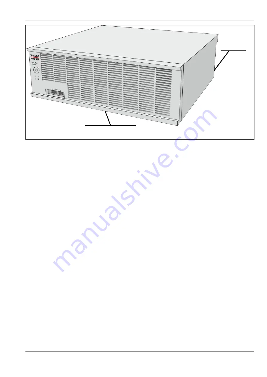
In order to ensure that correct ventilation continues to be guaranteed, the following minimum distances 
must be maintained, even with free convection (see illustration above)n:

To the rear: 60 mm
To the front: 50 mm

01750341829F

6-2

Summary of Contents for BEETLE/M-III

Page 1: ...BEETLE M III CPU Haswell K1 K2 Sky Lake M1 M2 Braswell O1 Coffee Lake R1 R2 Operator Manual 01750341829F...

Page 2: ...ed This document should be treated as confidential material for security reasons Any unauthorized disclosure or use of confidential material may violate the U S Theft of Trade Secrets provisions of Se...

Page 3: ...he BEETLE M III 7 1 7 1 Basic setting 7 1 8 External view 8 1 8 1 On Off button 8 1 8 2 Light emitting diodes 8 2 8 3 USB Universal Serial Bus A 8 3 8 4 External view with front hard disk access optio...

Page 4: ...dUSB Hub optional 15 1 16 COM5 COM6 interfaces optional 16 1 17 USB C card optional for an R1 R2 motherboard 17 1 18 Accumulator optional 18 1 18 1 Safety in the event of power failure 18 1 18 2 Repla...

Page 5: ...tal device pursuant to part 15 of the FCC Rules These limits are designed to provide reasonable protection against harmful interference when the equipment is operated in a commercial environment This...

Page 6: ...warning note describes a hazard with a medium degree of risk which if not avoided could result in death or grave bodily injury CAUTION This warning note describes a hazard with a low degree of risk wh...

Page 7: ...Touch sub assemblies with ESD only at their edges and do not touch any components Do not touch any connector pins or conductor paths on an electrostatic discharge sensitive assem bly 3 1 3 1 Safety I...

Page 8: ...al Cus tomer Service at Diebold Nixdorf International GmbH or the authorized service partner of your re tailer An explosion hazard exists if the lithium battery of the device is replaced incorrectly O...

Page 9: ...ut your BEETLE M III or other products and solutions of Diebold Nixdorf please visit us on the Internet 4 1 4 1 About This Manual The objective of this document is to aid you in the use of the system...

Page 10: ...andard Environmentally friendly product design and development The system is manufactured without the use of CFC and CHC and the majority of the components and materials used in its manufacture are re...

Page 11: ...n doing so connect various printers use the POS workplace with various screen displays utilize cash drawers in various design versions connect various keyboards order a BEETLE M III with a built in ba...

Page 12: ...el shown here on the underside of the housing The serial number is positioned next to the barcode on the label We recommended keeping the original packaging for any subsequent shipment that may be req...

Page 13: ...h provided with a anti slip rubber foil 6 2 2 6 2 2 Vertical In order to ensure that correct ventilation continues to be guaranteed the following minimum distances must be maintained even with free co...

Page 14: ...ning the cable cover You should remove the necessary cable entries before attaching the optionally orderable cable cover to the device Their removal is individually dependent on how and which cables y...

Page 15: ...To mount the cable cover set the two webs into the two rails see arrows on the rear of your BEETLE M III 1 Rails Hang up the cable cover on the left hand side Place the web in the plate on the other s...

Page 16: ...Before switching on Press this forward so that the cable cover closes flat 01750341829F 6 5...

Page 17: ...cket on the rear of the device Now insert the other cable end into the protective contact electrical socket s of the facility installation 1 On Off switch 2 Power supply To switch the device on briefl...

Page 18: ...tion shows the BEETLE M III from the front 1 On Off button 2 Power LED 3 2 USB interfaces 8 1 8 1 On Off button If the power supply unit is equipped with current then the system is switched on by pres...

Page 19: ...ashes briefly 4 x After a pause 100 ms on 900 ms off 100 ms on 900 ms off 100 ms on 900 ms off 100 ms on 4750 ms off POWER ON flashes briefly 2 x After a pause 100 ms on 100 ms off 100 ms on 700 ms of...

Page 20: ...and cables that are in accordance with the valid USB specifications are per mitted to be connected to the USB interfaces 8 4 8 4 External view with front hard disk access optional 1 LEDs for HDD1 HDD2...

Page 21: ...t the appliance from the supply voltage switch off the device and pull out the power plug of the power supply unit 1 PoweredUSB 24 V 2 RJ12 cash drawer 3 Power plug 9 1 1 9 1 1 PoweredUSB 24 V USB per...

Page 22: ...locked The power supply P24V 5 15 of the cash drawer is provided through this socket NOTE Please ensure that the plug has a tight contact with the socket because otherwise it can lead to malfunctions...

Page 23: ...may not be plugged into the system when it is switched on Example of a connecting orifice plate 1 3 x D Sub COM2 COM4 inter faces with power supply or 5 x D Sub 2 Display 2 DVI D PLINK2 with RMT for o...

Page 24: ...cated power supply to the COM1 interface COM1 is designed as a 9 pin D sub plug If you connect scales to the BEETLE M III which are not supplied by DN then you must acquire a DN license for the driver...

Page 25: ...not react the display switches off FW2 05 The system switches itself off the display re mains switched on RMT disabled Wake on PLINK RMT enabled OFF The system does not react The display remains off...

Page 26: ...hics cards or monitors USB can provide the required power for devices with little wattage such as phones or keyboards NOTE To determine which USB ports you have available please refer to the respectiv...

Page 27: ...be con nected to the pink socket Mic You can adjust the required volume through the software in the operating system or through the operat ing system itself for example the Windows operating system fe...

Page 28: ...tional 1 Power supply unit with fan 2 Air duct not applicable for a BEETLE M III with an O1 motherboard 3 Powered USB hub optional 4 Carrier with hard disk s 2 5 or 3 5 5 Two Front USB 6 Extension boa...

Page 29: ...uct not with a BEETLE M III with a O1 Motherboard 3 Carrier with hard disk s SSD s 4 PoweredUSB Hub with 3 PoweredUSB ports 5 Accumulator 6 Battery Backup Unit BBU 7 Extension board with three Powered...

Page 30: ...s of the house installation Pull all data communications cables out of the plug connections of the data networks Disengage all cables at the devices The Mini DIN plugs with Diebold Nixdorf key boards...

Page 31: ...gaging cables The electrically supplied USB plug is disengaged by pressing on the spring marked with the arrow Interface connector COM DVI VGA with knurled screw can be disengaged by hand 01750341829F...

Page 32: ...Disengaging cables To loosen a RJ45 plug press the tab above the plug see arrow downwards 01750341829F 11 3...

Page 33: ...are to ensure that the device is switched off and that the supply voltage plug is pulled out Remove any installed cable cover Disengage the knurled screws on the rear of the system Slide the housing c...

Page 34: ...Removing the housing cover Lift off the cover upwards Set it aside 01750341829F 12 2...

Page 35: ...ressed like a hard disk however they do not contain a rotating plate Instead they contain memory modules that are comparable with the elec tronic components inside a USB stick 13 1 13 1 Replacing a 3...

Page 36: ...Storage Media Fold open the data medium upwards and pull the data cable and the power supply cable 1 Power supply cable 2 Data cable Remove the hard disk carrier 01750341829F 13 2...

Page 37: ...ews of the respective hard disk by using a Phillips head screwdriver NOTE Use utmost caution when handling the hard disk including at the time of assembly and do not touch any exposed electronics Repl...

Page 38: ...DD is located at the top and the terminal strip faces to the right 1 Circuit board 2 Terminal strip Re install the hard disk holder following the steps in reverse order 13 2 13 2 Replacing two 2 5 dat...

Page 39: ...Storage Media Fold open the data medium upwards and pull the data cables and the power supply cable 1 Power supply cable 2 Data cable Remove the hard disk carrier 01750341829F 13 5...

Page 40: ...Storage Media Disengage the four screws of each hard disk with a Torx screwdriver Use one hand to support the hard disk when disengaging the screws 01750341829F 13 6...

Page 41: ...e hard disks including at the time of assembly and do not touch any exposed electronics Replace the hard disks Fasten the new hard disks using the screws removed earlier Observe the correct mounting p...

Page 42: ...Storage Media When inserting the hard disk into the carrier take care to ensure that the terminal strip is facing the openings in the side of the carrier 1 Terminal strip 01750341829F 13 8...

Page 43: ...disk s with frontal access First take care to ensure that the device is switched off and that the supply voltage plug is pulled out Open the front orifice plate by pressing the unlocking mechanism to...

Page 44: ...rage Media Set the orifice plate to the side Unlock the hard disks using the key provided note the interlock sym bols Pull out the carrier along with the hard disk using the green belt 01750341829F 13...

Page 45: ...Storage Media 01750341829F 13 11...

Page 46: ...take care to ensure that the terminal strip is at the back and that the label appears at the top Also take care to ensure that the knobs of the carrier fit into the re spective opening in the hard dis...

Page 47: ...4 13 4 Replacing the M 2 memory Switch off the device and remove the mains plug Remove the body cover Remove the screw with a Phillips head screwdriver PHO1 see arrow Pull the memory module out to the...

Page 48: ...E Observe the instructions regarding electrostatic discharge sensitive assemblies see chapter Electrostatic discharge sensitive components Fold open the hard disk carrier upwards and pull the data cab...

Page 49: ...Replacing a 3 5 SATA hard disk Remove the four screws of the 3 5 hard disk with a Phillips head screwdriver Re install the hard disk holder following the steps in reverse order 01750341829F 14 2...

Page 50: ...age devices e g hard disks can also be connected via a USB port Powered USB ports can also be used as USB A sockets BEETLE M III with a K1 K2 M1 M2 or R1 R2 motherboard BEETLE M III with an O1 motherb...

Page 51: ...tionally avail able Here is an example of a BEETLE M III with a K1 K2 M1 M2 or R1 R2 motherboard Scanners customer displays or operator displays that do not have a dedicated power supply are con necte...

Page 52: ...17 17 USB C card optional for an R1 R2 motherboard A USB C card can optionally be installed in this device The USB C card is installed in the central PCI slot see illustration 01750341829F 17 1...

Page 53: ...is approx 6 hours after commissioning The battery will only be charged if the system is switched on and the system software Wincor UPS Software under Windows Linux is configured and loaded trickle ch...

Page 54: ...ll discharge when the system is placed in storage If the device has been stored in excess of three months before being used for the first time you will need to charge the battery as it will discharge...

Page 55: ...years CAUTION First take care to ensure that the device is switched off and that the supply voltage plug is pulled out Remove the cable cover at the rear of the housing Disengage the two knurled screw...

Page 56: ...Accumulator optional Take care to ensure that the latches at the top are released Pull the plug from the socket 1 socket 2 plug 3 battery cable Lift and remove the clip if installed 01750341829F 18 4...

Page 57: ...e battery slightly at the front 1 and remove it from the system at an angle 2 Replace the battery and plug the battery cable into the socket Mount the clip optional approx 20 mm 0 79 from the rear of...

Page 58: ...m has been started up Observe the necessary settings after replacing the battery see the following chapter 18 3 18 3 Settings after the replacement The following settings must be implemented in order...

Page 59: ...onal Here in the example the text appears in English in a German language version it would be displayed in German Press the folder WINCOR UPS SOFTWARE The folder opens Press on UPS SOFTWARE MONITOR 01...

Page 60: ...Accumulator optional The menu appears in the following Select the menu item LocalUPSMAN via TCP IP 01750341829F 18 8...

Page 61: ...Accumulator optional The UPS monitor opens 01750341829F 18 9...

Page 62: ...Accumulator optional Press the red button at top in the menu strip see arrow Click on the Start new battery charge cycle but ton see arrow in the Remote Functions menu 01750341829F 18 10...

Page 63: ...d side of the motherboard Grasp the air duct and pull it upwards 1 so that you can access the RAM socket on the motherboard The removal of the air duct does not apply to a BEETLE M III with an O1 moth...

Page 64: ...previous position and insert the previously removed cables Close the device by mounting the housing cover sliding it into the front guide and fastening it place with the knurled screws Now insert the...

Page 65: ...to be started This means that each medium is is assigned a logical drive depending on the configuration of your system The following media can be assigned to a drive Network Hard disk SSD USB drive O...

Page 66: ...1 F to 104 F 0 C to 40 C with a R1 R2 Motherboard Processors K Motherboard Celeron G1820 Core i3 4330 Core i5 4570S Intel Pentium G3420 2x 3 3 GHz M Motherboard Skylake Intel Core i5 6500 4x 3 2 3 6 G...

Page 67: ...via powered USB hub or 3 x 12 V powered USB hub Graphics adapter 1x VGA max resolution 1920 x 2000 pixels 60 Hz 2x PLINK2 DVI D max resolution 1920 x 1200 pixels 60 Hz K1 M1 Max 3 displays for simulta...

Page 68: ...weredUSB on the power supply unit Optional 4 x 12 V via PoweredUSB Hub Graphics adapter 1x VGA Resolution max 1920 x 2000 Pixel 60 Hz 2x PLINK2 DVI D Resolution max 1920 x 1200 Pixel 60 Hz O1 Max 3 di...

Page 69: ...ernate mode with USB3 1 Gen1 Gen2 DP and PD PD2 0 with 5 V and 12 V only and 3 A as optional TYPEC extension Max support USB3 1 gen2 on R1 USB3 1 gen1 on R2 Graphics adapter 1x VGA max resolution 1920...

Page 70: ...ceed past 5 A Every COM 600 mA total of 900 mA Every PoweredUSB Every PoweredUSB 12 V 1 5 A total of 2 A max 3 A TFT LCD display Max 5 A 12 V The 24 V PoweredUSB interface is provided for the operatio...

Page 71: ...ponents CFC CHC Fluorinated chlorinated hydrocarbons chlorinated hydrocarbons GS Tested Safety HDD Hard Disk Drive IEC International Electrotechnical Commission ISO speed ratings International Organis...

Page 72: ...Abbreviations USB Universal Serial Bus VDE VDE Association for Electrical Electronic Information Technologies VGA Ultra extended graphics array wide 01750341829F 22 2...

Page 73: ...21 2 21 3 21 4 L LAN 9 6 21 2 21 3 21 4 light emitting diode 8 2 Line In 9 7 Line Out 9 7 lithium battery 3 2 LPT 21 2 21 3 21 4 M memory extension 19 1 microphone 9 7 21 2 21 3 21 4 Mini DIN plugs 11...

Page 74: ...DIEBOLD NIXDORF 5995 Mayfair Road North Canton OH 44720 United States 2020 Diebold Nixdorf Incorporated All Rights Reserved...

Reviews: