E
E
N
N
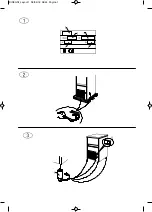
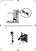
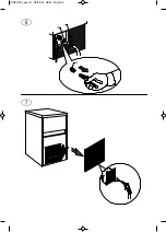
Lift the appliance using equipment fit to bear its weight. Separate the appliance from the wooden pallet and fit the supplied feet
into the housings on the base plate provided for the purpose (6 in Fig. 3).
Use a spirit level to ensure that the appliance is standing perfectly level. If necessary, adjust the feet.
5 INSTALLATION
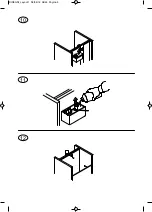
5.1 CONNECTION DIAGRAM (Fig. 4)
7. electrical connection controlled by omnipolar circuit-breaker with residual current device
8. water tap
9. water supply pipe
10. water drainage pipe
5.2 POSITIONING
The appliance must be installed in a hygienically clean location; avoid premises such as cellars and storerooms,
because poor hygiene promotes the formation and proliferation of bacteria in the appliance.
The appliance can operate at an ambient temperature of between 10°C and 43°C.
The best performance will be obtained by installing the appliance in a place with an ambient temperature of between
10°C and 35°C and a water temperature of between 3°C and 25°C.
Avoid direct exposure to sunlight and do not install near heat sources.
This appliance:
•
must be
installed in a place where it can be supervised by skilled personnel
• must not be used outdoors
• must not be installed in damp places or where it is liable to be sprayed with water
• must not be cleaned with jets of water
• must be allowed a clearance of least 5 cm all around
5.3 CONNECTION TO THE WATER MAINS
IMPORTANT:
•
the appliance must be connected to the water mains by professionally qualified personnel in accordance with the
Manufacturer’s instructions
•
this appliance must be only be supplied with cold water for human consumption (drinking water)
•
the operating pressure must be between 0.1 and 0.6 MPa
•
a tap must be installed between the water mains and the feed pipe of the appliance, so that the water supply may be shut off if
necessary
•
where the feed water is particularly hard, you are advised to install a polyvalent cartridge filter. Any solid particles (e.g. sand)
may be eliminated by installing a mechanical filter, which must be periodically inspected and cleaned. These devices must
comply with the standards in force in the Country of use
•
never turn the water supply tap off when the appliance is working
•
only new hose-sets supplied with the appliance are to be used to connect the appliance to water mains, old hose-sets should
not be reused
•
Is forbidden install the machine to
De-ionized or Reverse Osmosis Water
5.3.a FILLING WITH WATER (Fig. 5)
Insert the special seals provided (12) in the two threaded ring nuts (11) of the water supply pipe (9) supplied with the appliance.
Without exerting excessive force (otherwise the unions could crack), firmly tighten one of the threaded ring nuts on the outlet of
the solenoid valve located in the rear of the appliance. The other threaded ring nut must be screwed to the water tap (8); this
too must be provided with a thread.
5.3.b DRAIN (Fig. 5)
Fix the water drain pipe (10) in the housing provided on the rear of the appliance. Make sure that:
• the pipe is a hose
• the internal diameter is 22 mm, as required
• the water drain hose is not throttled at any point throughout its length
• the drain hose slopes downwards by at least 15%
It is advisable to drain the water straight into an open drain trap.
5.4 CONNECTION TO THE ELECTRICITY MAINS
IMPORTANT:
Summary of Contents for ICE115AS-R2
Page 1: ...Mod ICE115AS R2 Production code GB903A HC 08 2018 ...
Page 15: ...DISEGNI_Layout 1 06 04 18 08 44 Pagina 1 ...
Page 16: ...DISEGNI_Layout 1 06 04 18 08 44 Pagina 2 ...
Page 17: ...DISEGNI_Layout 1 06 04 18 08 44 Pagina 3 ...
Page 18: ...8 9 DISEGNI_Layout 1 06 04 18 08 44 Pagina 4 ...
Page 19: ...10 11 12 DISEGNI_Layout 1 06 04 18 08 44 Pagina 5 ...


