background image

<17m>

HVC18


<10m>

HVC28


WARNINGS: 

(1) 

Bolts and set screws on antenna and mounting bracket may 

loosen from vehicle and road vibration. Be sure to check periodi-
cally to ensure they are fastened securely. 

(2) 

Avoid obstacles such as tree branches or low overpasses; 

impact with these obstacles will cause antenna damage. 

(3) 

The HV7A is not recommended for either magnet type mounts 

or installation on large GVW vehicles. 

(4) 

Avoid touching antenna while transmitting. 

(5) 

Do not scratch or remove rubber covering on loading coil 

sections. 

(6) 

Avoid driving with antenna in folded position. 

Typical VSWR Charts 

<40m>

HVC7


<20m>

HVC14


<15m>

HVC21


6M/50 MHz


2.0 

1.1 

1.5 

-2 MHz 

f

o


+2 MHz 

—20m 

—17m 

—15m 

—10m 

HVC Loading Coils 

— 40m 

f

o


-14 KHz 

+14 KHz 

f

o


-30 KHz 

+30 KHz 

f

o


-90 KHz 

+90 KHz 

f

o


-70 KHz 

+70 KHz 

f

o


-195 KHz 

+195 KHz 

Tuning element 

Tuning 

Tuning 

Tuning 

Tuning 

Summary of Contents for HV7A

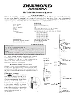
Page 1: ...s that at least one loading coil is mounted at the top end VSWR may be out of specification without the coil s 1 Choose mounting location to insure maximum strength of mount and proper vehicle ground to yield best performance 2 Assemble HV7A with desired loading coil and install on vehicle mount HVC28 10m coil is included in package NOTE Metric Hex wrenches are enclosed READTHISBEFORETUNING ANTENN...

Page 2: ... coil should point to the rear The VSWR will change slightly by adding a coil horizontal therefore it is best to check your VSWR readings to verify adjustment To add loading coil in horizontal position simply remove Philips head screw from opposite side of 981116 50 MHz Element support bracket and screw HVC coil into position See Illustration All HVC loading coils have lock nut on threaded end to ...

Page 3: ...damage 3 The HV7A is not recommended for either magnet type mounts or installation on large GVW vehicles 4 Avoid touching antenna while transmitting 5 Do not scratch or remove rubber covering on loading coil sections 6 Avoid driving with antenna in folded position TypicalVSWRCharts 40m HVC7 20m HVC14 15m HVC21 6M 50 MHz 2 0 1 1 1 5 2 MHz fo 2 MHz 20m 17m 15m 10m HVCLoadingCoils 40m fo 14KHz 14KHz ...

Page 4: ...uency Interference Tips How to find it and fix it The book is available from your favorite amateur radio dealer or ARRL headquarters MX62M Duplexer LPF 1 6 56 HPF 76 470 Power 200w CW 600w PEP Connectors Mix UHF F Ports UHF M w 12 cable K400C Trunk HatchbackMount Deluxe UHF type base Dual axis adjustable 6 RG316 Teflon Coax w PL 259 Use Diamond Model C110 for front radio installations HV7AAccessor...

Reviews: