background image

AIRCRAFT

DA 40 Series AMM

Temporary Revision

NLG Inspection & Maintenance

100 hr items marked X* apply to US registered airplanes only

Inspection Items

100 200 1000 2000 Time Initials

23.

Examine these components on LH and RH sides for
dis-bonding, delamination and damage: 

The center section top and bottom shells.

The outer faces of the front and rear main
bulkheads. Look specially in the area of the bushes
for the main pins.

The front, middle and rear outer ribs.

The main landing gear rib.

The front and rear closing ribs.

The rear web.

X

24.

Examine the inner faces of the front and rear main
bulkheads with the wings removed. Look specially in
the area of the bushes for the main bolts. (See also
Paragraph 6).

X

25.

Install the access panels for the main landing gear legs.
(Refer to Section 52-40).

X*

X

X

X

26.

Remove the access panel for the nose landing gear
leg. (Refer to Section 52-40). Inspect the nose landing
gear leg for cracks, corrosion, paint condition, and
deformation.

X

X

X

X

27.

Examine the nose-wheel assembly. Look specially for
incorrect attachment, cracks and deformation.

X

X

X

X

28.

Examine the nose-gear journal-bearings in the bottom
of the fuselage. Look specially for play.

X*

X

X

X

29.

Examine the journals in the elastomeric spring. Look
specially for play.

X

X

X

X

30.

Examine the spherical bearing at the top of the
elastomeric spring. Look specially for play.

X

X

X

X

Doc # 6.02.01
AMM-TR-MÄM 40-1037

05-28-50

Page 6

13 Jul 2020

Summary of Contents for DA 40 Series

Page 1: ...in conjunction with the Airplane Maintenance Manual AMM until this temporary revision has been incorporated into the AMM The limitations and information contained herein either supplement or in the ca...

Page 2: ...temporary revision on the yellow RECORD OF REVISIONS sheet at the front of the AMM Keep this temporary revision until the information has been incorporated into the DA 40 AMM Pages of this TR Insert...

Page 3: ...at X X X X 2 Examine these NACA air inlets for blockage One in the left stub wing Two in the forward fuselage LH and RH optional O M 40 099 X X X X 3 Examine the canopy Make sure the canopy lock mecha...

Page 4: ...e window and the door frame Refer to Section 56 10 X X X X 8 Examine the rear window on the RH side Examine the acrylic glass window for damage Look specially for cracks Examine the bonding between th...

Page 5: ...y for wear Minimum thickness according to Cleveland Parker Maintenance Manual latest revision X X X X 18 Remove the access panels for the main landing gear legs Refer to Section 52 40 X X X X 19 Exami...

Page 6: ...removed Look specially in the area of the bushes for the main bolts See also Paragraph 6 X 25 Install the access panels for the main landing gear legs Refer to Section 52 40 X X X X 26 Remove the acce...

Page 7: ...ar Replace the center tube if a radial wear limit depth measured of 0 8 mm is exceeded Remove the elastomer elements in the event that they are worn or cracks are found Refer to Section 32 20 Adjustme...

Page 8: ...l the filter bowl Refer to Section 28 20 for the Lycoming version or Section 28 21 for the TAE version Do a check for fuel leakage X X X X 41 Examine the fuel pump electrical cables Look specially for...

Page 9: ...B Procedure Detail Steps Work Items Key Items 1 Remove the access panels for the main and nose landing gear Refer to Section 52 40 2 Examine the landing gear fittings Look specially for cracks Use a m...

Page 10: ...ook specially for Deformation of the upper cross bar of the engine mount Nose wheel strut axle area Remove the fork assembly Refer to Section 32 20 Use a flashlight and a 10X magnifier Pay special att...

Page 11: ...llation of the elastomer pack Refer to Section 32 20 11 Examine the top hat profile in the bottom of the fuselage for delamination and disbonding Look specially in the area of the bearings for the nos...

Page 12: ...f the adjustable front seats O M 40 252 or O M 40 375 are installed WARNING DO NOT LOOSEN THE LEVER FOR THE ADJUSTABLE BACKREST OF THE FRONT SEATS UNINTENTIONALLY THE SPRING LOADED BACKREST MAY SNAP F...

Page 13: ...AIRCRAFT DA 40 Series AMM Temporary Revision NLG Inspection Maintenance Figure 1 Hard Landing Check Areas Nose Landing Gear and Firewall Doc 6 02 01 AMM TR M M 40 1037 05 50 00 Page 13 13 Jul 2020...

Page 14: ...AIRCRAFT DA 40 Series AMM Temporary Revision NLG Inspection Maintenance Figure 2 Hard Landing Check Areas Main Landing Gear Doc 6 02 01 AMM TR M M 40 1037 05 50 00 Page 14 13 Jul 2020...

Page 15: ...nt fuselage just aft of the nose wheel mounting 3 Remove the nose wheel fairing 4 Adjust the nose wheel fork pivot nut The nose wheel must just castor when a force of 30 50 N 6 75 11 25 lb is applied...

Page 16: ...Nut Apply a Force of 30 50 N 6 75 11 25 lb in both Directions along the Line of the Axle 6 Nose Wheel Balancing Always have the nose wheel balanced before installation Figure 4 Adjust the Nose Wheel...

Page 17: ...tems References 1 Clean the NLG strut and fork bushing of any dirt or residue 2 Install the fork assembly on the NLG strut axle as follows Install the fork assembly to the NLG strut Install the stop p...

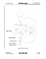
Page 18: ...AIRCRAFT DA 40 Series AMM Temporary Revision NLG Inspection Maintenance Figure 5 NLG Fork Assembly Doc 6 02 01 AMM TR M M 40 1037 32 20 00 Page 18 13 Jul 2020...

Reviews: