Dialog DA14585 User Manual Download Page 18


UM-B-048 


DA14585/DA14586 Getting Started Guide with the Basic Development Kit   


User Manual 

Revision 2.0 

09-Jul-2018 

CFR0012-00 Rev 2  

18 of 29 

© 2018 Dialog Semiconductor 


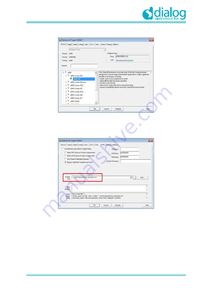
Figure 19: Blinky Project Options 

4. 

Click on 

Linker

. Scatter files (.sct) are used for selecting memory areas. 


Figure 20: Blinky Project Scatter File 

5. 

Click on 

Debug

 and ensure 

J-LINK/J-TRACE Cortex

 is selected and that the 

Initialization File


is set correctly to 

.sysram.ini

Summary of Contents for DA14585

Page 1: ...the Basic Development Kit UM B 048 Abstract This guide is intended to help customers setup the hardware development environment install required software download and run an example application on the...

Page 2: ...Installation 10 7 1 Requirements of the Development PC 10 7 2 Driver Installation 10 7 3 Configuring the Serial Port for UART 11 7 3 1 Using Serial Port 11 7 4 Troubleshooting 12 8 Software Developmen...

Page 3: ...ectory 17 Figure 18 Blinky Project Keil Workspace 17 Figure 19 Blinky Project Options 18 Figure 20 Blinky Project Scatter File 18 Figure 21 Blinky Project Debug Option 19 Figure 22 Blinky Project Jlin...

Page 4: ...ing Diode OS Operating System OTP One Time Programmable PC Personal Computer RF Radio frequency SDK Software Development Kit SoC System on Chip SPI Serial Peripheral Interface SRAM Static Random Acces...

Page 5: ...n overview of the DA14585 586 Basic Development Kit Board and describe the setup of the hardware and installation of the software tools to fully use the board The following hardware and software eleme...

Page 6: ...fer to the respective documents on the portal 6 1 The Basic Kit board Figure 1 illustrates the physical layout of the Basic Kit board The basic Kit board provides the necessary hardware to enable Full...

Page 7: ...own in Figure 4 Figure 4 Data direction of UART within J4 Note UART connectivity is enabled by shorting header as presented in Figure 2 UART connection between DA14585 586 and the MCU that provides co...

Page 8: ...velopment Kit User Manual Revision 2 0 09 Jul 2018 CFR0012 00 Rev 2 8 of 29 2018 Dialog Semiconductor Figure 5 DA14585 586 Boot from external SPI memory 6 3 Board Layout The layout of the basic board...

Page 9: ...is done through jumpers J5 3 pins connector DA14585 586 can be supplied by either 3 3V generated from on the development kit or by coin cell battery applied on the bottom side of the development kit J...

Page 10: ...on to a host PC running Microsoft Windows the system will detect several devices and will automatically install all necessary drivers If the system is configured to use Windows Update this may take se...

Page 11: ...hed it is necessary to verify the UART connection between the two nodes On the Windows host Tera Term can be used to validate the connection to the by Basic Development Kit following these steps 1 Con...

Page 12: ...connection to PC some possible solutions might be Check for possible cabling issues by using a different USB cable Connect the two elements using a different USB port on the host PC Note If none of th...

Page 13: ...single stepping setting breakpoints software download and many more For more details on the debugger capabilities visit https www segger com 8 1 SmartSnippets Installation The installation procedure...

Page 14: ...artSnippets Studio and click Next Figure 13 Select SmartSnippets Studio Install Directory The SmartSnippets Studio is installed Note The default Windows installation folder for SmartSnippets Studio is...

Page 15: ...tools can be run as a Lite Evaluation version without a product license see Figure 14 File License Management This Lite Evaluation version has a 32 kB of code in ROM limitation Figure 14 Keil Lite ve...

Page 16: ...environment on any of the DA14585 586 devices Make sure that you have all required tools installed as described in Section 7 and Section 8 The DA14585 586 Software Development Kit SDK includes example...

Page 17: ...directory projects target_apps peripheral_examples blinky Keil_5 double click blinky uvproj to open the project in Keil Figure 17 Blinky Project directory The development environment should look like...

Page 18: ...0012 00 Rev 2 18 of 29 2018 Dialog Semiconductor Figure 19 Blinky Project Options 4 Click on Linker Scatter files sct are used for selecting memory areas Figure 20 Blinky Project Scatter File 5 Click...

Page 19: ...ctor Figure 21 Blinky Project Debug Option 6 Click on Settings and check that the SW Device has been detected correctly Figure 22 Blinky Project Jlink setup 7 Click OK to save the settings in both win...

Page 20: ...otherboard as shown in Figure 8 Check the COM number on your PC 10 Open Tera Term choose the COM port from step 9 and click OK 11 Select Setup Serial Port to configure the port as shown in Table 1 12...

Page 21: ...board Figure 27 Blinky Project Blinky message on COM28 terminal 9 2 The Barebone BLE Example Application The Barebone BLE example application demonstrates basic BLE procedures such as advertising conn...

Page 22: ...hows the Keil project layout Figure 29 Barebone BLE KEIL Project Layout 3 To execute the code and run the example repeat steps 3 to 14 in The Blinky Peripheral Example Application The barebone applica...

Page 23: ...2018 Dialog Semiconductor Figure 30 Barebone BLE Interacting with BLE Application Your BLE application is now running and advertising using the default advertiser string DIALOG BRBN Note In this examp...

Page 24: ...mware or any issue with SDK operation refer to the DA1458x 68x Development Kit J Link Interface Application Note AN B 052 Note If none of these actions resolved the issue please contact Dialog Softwar...

Page 25: ...it Figure 31 Hardware Settings for Basic Development Kit 10 2 Appendix B Latency Timer of the FTDI cable If an external FTDI cable is used to burn the OTP or to download the image into the external me...

Page 26: ...of the DA14585 and DA14586 Basic Development Kit is made in such a way that the microcontroller can be isolated completely from the rest of the board This is illustrated in the block diagram shown in...

Page 27: ...Meter to jumper J5 2 Mount the jumpers needed for downloading the software 3 Download the software 4 Start the software 5 Wait till software has reached Deep Sleep 6 Dismount all the jumpers Now almos...

Page 28: ...tor reserves the right to change without notice the information published in this document including without limitation the specification and the design of the related semiconductor products software...

Page 29: ...uctor K K Phone 81 3 5769 5100 Taiwan Dialog Semiconductor Taiwan Phone 886 281 786 222 Hong Kong Dialog Semiconductor Hong Kong Phone 852 2607 4271 Korea Dialog Semiconductor Korea Phone 82 2 3469 82...

Reviews: