DSP-22-2_MAN_E
12/10/2020
Page 1 of 25
Pros Who Know Trust Diablo
User Manual
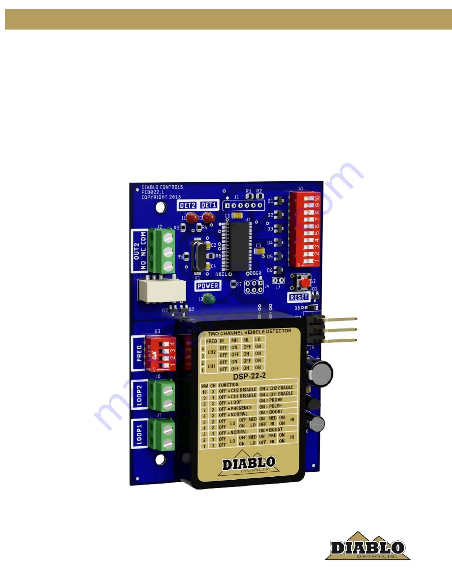
DSP-22-2
Low Power, Dual Channel Vehicle Detector with Support for the Free Exit Probe
Page 1: ...DSP 22 2_MAN_E 12 10 2020 Page 1 of 25 Pros Who Know Trust Diablo User Manual DSP 22 2 Low Power Dual Channel Vehicle Detector with Support for the Free Exit Probe ...
Page 2: ...6 10 Channel 2 Presence Pulse DIP Switch 7 10 Channel 2 Loop Probe DIP Switch 8 11 Channel 2 Frequency S3 DIP Switches 3 and 4 11 Indicators 12 3 Installation 15 General Rules and Best Practices for Inductive Loops 15 Detector Installation 16 Loop Installation 17 Free Exit Probe Installation 20 4 Troubleshooting 22 No Power LED 22 Detect LED Flashes On Once Every Two Seconds 22 Detect LED Flashes ...
Page 3: ... DSP 22 2_MAN_E Figures Figure 1 Product Views 4 Figure 2 Physical Dimensions 7 Figure 3 Loop Installation 19 Figure 4 Saw Cut for Home Run Exit and Chiseled Corner for Home Run Exit 19 Figure 5 Typical Free Exit Probe Installation 20 ...
Page 4: ... The detector is powered by a high performance 8 bit microcontroller that does not skimp on performance The DSP 22 2 detector has a small footprint and was designed to directly plug into many DoorKing operators The detector uses a 3 pin Molex connector for its power connections and the Channel 1 solid state output The Channel 2 relay outputs have separate screw terminals for wired connections Figu...
Page 5: ...r frequency settings available The actual loop frequency is dependent on loop circuit inductance Channel 1 S3 DIP Switch Frequency 1 2 OFF OFF High ON OFF Medium High OFF ON Medium Low ON ON Low Channel 2 S3 DIP Switch Frequency 3 4 OFF OFF High ON OFF Medium High OFF ON Medium Low ON ON Low B Pulse Output 250ms 15ms Response Time 181 ms typical 314 ms worst case Vehicle Hold Time Both channels wi...
Page 6: ...oltage 30 volts Maximum Voltage Drop Across Active Output 0 3 volts Relay Output Rating 30 VDC 2 amps resistive 110 VDC 0 3 amps resistive 125 VAC 0 5 amps resistive Current Draw No Channel in Detect 1 62 milliamps typical 20VDC Channel 1 in Detect 23 94 milliamps typical 20VDC Channel 2 in Detect 30 75 milliamps typical 20VDC Both Channels in Detect 33 60 milliamps typical 20VDC Environmental Dat...
Page 7: ... of 25 DSP 22 2_MAN_E Mechanical Data Mounting Position Any Housing Material Lexan Detector Size 4 300 inches High x 2 950 inches Wide x 820 inches Deep 109 22 mm High x 74 93 mm Wide x 20 83 mm Deep Figure 2 Physical Dimensions ...
Page 8: ... will turn off the channel 1 LED and turn off the channel 1 output The factory default is enabled DIP switch 9 ON Channel 1 Sensitivity DIP Switches 1 and 2 Channel 1 has four possible sensitivity levels In most situations the sensitivity setting medium high DIP switch 1 OFF and DIP switch 2 ON will work effectively For those situations where this setting is not sensitive enough raise the sensitiv...
Page 9: ...nected to the same DSP 22 2 detector can not interfere with each other as the detector will only turn on one of the loops at any point in time this is referred to as scanning To aid in mitigating inductive coupling each DSP 22 2 unit comes with two frequency switches for each channel They are binary coded allowing up to four different operating frequencies If there are suspicions that loops are in...
Page 10: ... in situations where high bed tractor trailer vehicles will be passing over the loop With this feature the detector may be able to detect the high bed portion of the vehicle without having to be overly sensitive and susceptible to false detections NOTE If detection of high bed tractor trailers is required correctly sized loops must be used DIP Switch 6 Function OFF Channel 2 Normal Sensitivity ON ...
Page 11: ...P Switch 7 Function OFF Channel 2 Presence Mode ON Channel 2 Pulse Mode Channel 2 Loop Probe DIP Switch 8 The DSP 22 2 is capable of operating with either a standard inductive loop or the new mini loop magnetometer As usual the inductive loop operates in both presence and pulse modes However the mini loop magnetometer can only operate in pulse mode and will automatically override any settings to t...
Page 12: ... milliseconds on for 500 milliseconds off for 500 milliseconds and then display its normal state High Speed Operation The LED is always on when the detector is in its high speed mode of operation Low Power Operation The LED will blink on once every 2 seconds when the detector is in its low power mode of operation Detect 1 LED The red Detect 1 LED is used to display the status of Channel 1 There ar...
Page 13: ... the status In the high speed mode of operation green LED is ON and the channel is not in detect the LED will flash on one two or three times depending upon the prior failure type When the detector is in the low power mode Green LED flashes on once every 2 seconds the channel Detect LED will flash on at the same time Detect 2 LED The red Detect 2 LED is used to display the status of Channel 2 Ther...
Page 14: ...sh three times every two seconds repeatedly for the duration of the fault If the fault is corrected the LED will display the appropriate Prior Fault indication Prior Fault The detector is equipped with the ability to remember prior faults that have occurred since the last power interruption or reset changing a DIP switch or the sensitivity The detector will hold this status for one week and then a...
Page 15: ...ed to reduce the loop wire bend angle to not exceed 45 degrees at any location 5 Use backer rod to hold the loop wire at the bottom of the saw cut before sealing the loop The backer rod should be cut into 1 inch pieces and one placed every foot or so as needed 6 If a loop installation will cross an expansion joint in the roadway surface some method of leaving some slack wire at the joint should be...
Page 16: ...f the source is overhead or below ground power lines the saw cut should be parallel to the short side of the loop The loop wire is placed in the saw cuts using a figure 8 motion A figure 8 loop will have more inductance that a similar sized conventional loop 14 If multiple loops are to be connected to the same detector there are several things to be aware of a Always connect multiple loops in seri...
Page 17: ...ring the loop should have a jacket of cross linked polyethylene or similar material that has very low moisture absorption properties This would be a wire with an XLP jacket such as XHHW THHN or similar wire types should never be used for loop wire The gauge of the wire to use depends on two factors Distance in cable feet from the loop to the detector and stresses the wire may see The gauge of the ...
Page 18: ... water finds its way in to these air pockets over time freeze thaw cycles can slowly jack the loop out of the saw slot causing loop failure The saw slot should be deep enough that the loop wire will have a minimum of of sealant over the top wire in the slot More is better Going too deep with the saw cut is also a concern Deep cuts in a road surface may impact the structural strength of the roadway...
Page 19: ...SP 22 2 User Manual Page 19 of 25 DSP 22 2_MAN_E Figure 3 Loop Installation Figure 4 Saw Cut for Home Run Exit and Chiseled Corner for Home Run Exit BACKER ROD PIECE LOOP WIRE SAW CUTS DETAIL A DETAIL B ...
Page 20: ...at it fits snugly in the saw slot Use a blunt object not a screwdriver to press the backer rod pieces down into the saw slot as far as they will go Keeping the loop wire at the bottom of the saw slot allows the loop sealant to provide the maximum amount of protection possible from foreign object penetration Never use a continuous piece of backer rod over the loop as this would prevent the loop sea...
Page 21: ..._MAN_E Side Detection Zone Placement NOTE When the roadway is greater than 11 feet wide requiring a greater detection zone you have the option to add a second Free Exit Probe to the opposing side of the roadway The probes must be wired in series ...
Page 22: ...s below 5 ohms the loop inductance should be checked This is done using an inductance meter The inductance of the loop should be less than 1500 microhenries It is very unusual to have a loop with an inductance value this high but it is possible with very large loops and many turns If the loop inductance value is above 1500 microhenries the loop will have to be replaced with a loop with less induct...
Page 23: ... the loop wire should be redone If there are any wire nuts used in the loop circuit remove them and replace with a crimp connection or preferably a soldered connection The open loop fault could also be a fatigued point in the loop wire This can occur at locations where the loop wires cross an expansion joint in the road surface Any place where the loop wires must move even if only a very tiny amou...
Page 24: ...sible source for electrical interference depending on its proximity to the loop and the amount of energy being used If you believe the loop is experiencing electrical interference turn off the device believed to be the source of the interference and see if the problem goes away Sometimes this is not possible and more technical means are needed to help identify the source Call Technical Support in ...
Page 25: ...gh and the red LED still does not come on and you have another operating detector swap the loops between a working detector and a failing detector If the problem follows the loop the loop is the problem If it stays in the same detector replace the detector Detect 1 and Detect 2 LEDs Flash Back and Forth The red Detect LEDs will flash back and forth when neither channel is enabled DIP switches 9 10...