background image

Appendix

%

Cable Specifications

%

-6

VS-05 Smart Camera Guide

Power Supply, 90-254 VAC, +5VDC

The Power Supply, 90-254 VAC, +5VDC ends in a 3-pin Micro-Change 
connector.

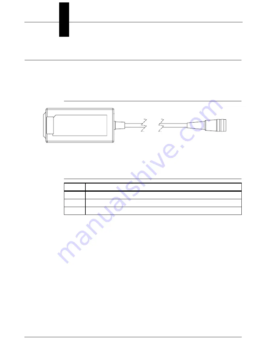
Figure B-5 shows the Power Supply, 90-254 VAC, +5VDC.

FIGURE B–4. 

Power Supply, 90-254 VAC, +5VDC

Table B-7 describes the signals for the Power Supply, +5VDC.

TABLE B–6. 

Power Supply, +5VDC Pin Assignments

Pin

Function

1

Ground (Black)

2

Shield (Bare)

3

+5VDC (White)

Summary of Contents for VS-05

Page 1: ...VS 05 Smart Camera Guide ...

Page 2: ...state herein that we are using the names only in an editorial fashion and to the benefit of the trademark owner with no intention of infringement Disclaimer The information and specifications described in this manual are subject to change without notice Latest Manual Version For the latest version of this manual see the Download Center on our web site at www di soric com Technical Support For tech...

Page 3: ...fits 1 2 Applications 1 3 Package Contents 1 3 VS 05 Smart Camera Models 1 4 Part Number Structure 1 4 CHAPTER 2 System Components 2 1 Hardware Components 2 1 Important Label Information 2 4 Mounting and Wiring the VS 05 Smart Camera 2 5 Status Indicators 2 10 AutoVision Button 2 11 Trigger Debounce 2 12 CHAPTER 3 Optics and Lighting 3 1 Optics 3 2 Illumination 3 3 ...

Page 4: ...lug Cable B 2 61 000105 01 Host Cable MS Connect 210 to Host Stripped to 9 Pin Socket B 3 VSID K 25S 9K 2 Communication Cable DB25 Plug to DB9 Socket B 6 VSID PS 24V ES Power Supply 90 254 VAC 24VDC USA Euro Plug B 8 APPENDIX C General Specifications C 1 Dimensions C 5 Field of View and Working Distance C 6 APPENDIX D Serial Commands D 1 APPENDIX E VS 05 Diagnostic Boot Mode D 1 ...

Page 5: ...ins detailed information about the VS 05 Smart Camera Manual Conventions The following typographical conventions are used throughout this manual Items emphasizing important information are bolded Menu selections menu items and entries in screen images are indicated as Run triggered Modify etc ...

Page 6: ...Preface 6 Vs 05 Smart Camera Guide ...

Page 7: ...VS 05 Smart Camera Guide 1 1 1 Introduction 1 CHAPTER 1 Introduction FIGURE 1 1 VS 05 Smart Camera ...

Page 8: ...utoVision button at the back of the VS 05 enables real time dynamic autofocus When an object is centered in the field of view and the AutoVision button is pressed the camera automatically adjusts focal distance and sets internal parameters to optimize image captures di soric AutoVision software designed for use with the VS 05 provides an intuitive interface step by step configuration and a library...

Page 9: ...on Packaging Robotics Auto ID Data Matrix and other 2D symbologies 1D OCR Package Contents Before you install AutoVision software and connect your VS 05 Smart Camera please take a moment to confirm that the following items are available VS 05 Smart Camera Your package contains one of the available models listed in Table 1 1 USB Type A to USB Type B Cable AutoVision Software Installation USB Drive ...

Page 10: ...US VS 05 Smart Camera USB SD SXGA Built In Light AutoVision VisionScape VS 05 BM3 3 US VS 05 Smart Camera USB HD SXGA Built In Light AutoVision VS 05E BM3 3 US VS 05 Smart Camera USB HD SXGA Built In Light AutoVision VisionScape VS 05 BM2 2 US VS 05 Smart Camera USB SD WVGA Built In Light AutoVision VS 05E BM3 2 US VS 05 Smart Camera USB SD WVGA Built In Light AutoVision VisionScape VS 05 BM2 3 US...

Page 11: ...ts inside Hardware Components Table 2 1 lists VS 05 Smart Camera hardware components TABLE 1 VS 05 Smart Camera Hardware Components Part Number Description Upgrade to VisionScape VS UP AV VS Upgrade from AutoVision to verifikation AM DPM VisionScape VS UP AV VS OCV Upgrade from AutoVision to full VisionScape verifikation AM DPM OCV Power Supply VSID PS IB Power Supply Interface Box 90 254 VAC 24VD...

Page 12: ...VSID IB S Interface Box VSID K 25S 9K 2 Communication Cable DB25 Plug to DB9 Socket 6 Mounting Options VSID BW 003 Through Hole Mount Bracket VSID BW 001 Side Mount Bracket VSID R90 001 Right Angle Mirror Kit VSID DIF 001 Diffuser Accessory Kit TABLE 1 1 VS 05 Smart Camera Hardware Components Continued Part Number Description ...

Page 13: ...e Components System Components 1 VS 05 Smart Camera Guide 3 Front Figure 1 1 shows the front of the VS 05 Smart Camera FIGURE 1 1 Front Base Figure 2 2 shows the base of the VS 05 Smart Camera FIGURE 1 2 Base ...

Page 14: ...t Camera has its own label which contains important information about that camera P N The di soric part number of your VS 05 Smart Camera S N The serial number of your VS 05 Smart Camera MAC The MAC address of your VS 05 Smart Camera Type The model type of your VS 05 Smart Camera USB I O cable attached AutoVision Button Status Indicators TRIG PASS FAIL MODE LINK ACT PWR ...

Page 15: ...era 1 is mounted at the optimal distance of 2 to 6 Mount the camera 1 as required by the application Connect the USB side of the camera cable 2 to the USB host cable 3 Connect the VSID A 24 5V S 4 to the VSID IB S 5 Connect the D sub side of the camera cable 2 to the VSID A 24 5V S 4 Connect the trigger 6 to the VSID IB S 5 Connect the power supply 7 to the VSID IB S 5 Plug in the power supply 7 7...

Page 16: ...Chapter 2 System Components 6 VS 05 Smart Camera Guide Direct Input Output Diagrams ...

Page 17: ...Mounting and Wiring the VS 05 Smart Camera System Components 1 VS 05 Smart Camera Guide 7 Isolated Trigger Input with VSID A 24 5V S ...

Page 18: ...Chapter 2 System Components 8 VS 05 Smart Camera Guide New Master Input with VSID A 24 5V S ...

Page 19: ...ments Refer to Table 2 3 when determining the power supply requirements for your camera TABLE 1 3 Camera Power Requirements Component 5VDC VS 05 Smart Camera WVGA 5VDC 5 200 mV p p max ripple 400 mA 5VDC typ 4 0 watts max VS 05 Smart Camera SXGA 5VDC 5 200 mV p p max ripple 465 mA 5VDC typ 4 5 watts max ...

Page 20: ...f the unit allows the user to center an object in the camera s field of view Beeper The beeper is an audible verification that either a Pass or a Fail has occurred TRIG On Steady Continuous Trigger Off Waiting for Trigger Event On Flashing Trigger Event PASS FAIL On Active State Off Inactive State MODE On Steady Unit Ready Off Unit Not Ready LINK ACT On Steady Link Established Off No Link Activity...

Page 21: ...bled pushing the AutoVision Button triggers the camera to capture an image 1st Position Blue Targeting Pattern The first AutoVision Button position turns the targeting system on This overrides any other targeting modes that have been configured 2nd Position Auto Calibration The second AutoVision Button position starts the Auto Calibration process which selects the appropriate photometry and focus ...

Page 22: ... Time is 0 which disables software debounce altogether The maximum value is 100000 100 ms Camera Definition File Example Camera Definition File Version 1 02 Camera Name VS 05 1280x1024 Name Displayed in Camdef Selection Dialog Digitizer Type 5000 Number associated with VS 05 SXGA Stride 1280 Image Width Rows 1024 Image Height X Offset 0 Image X Offset Y Offset 0 Image Y Offset Bits Per Pixel 8 Bit...

Page 23: ...5 Smart Camera Guide 13 IO Line Debounce Low Time 2000 usecs Focus Photometry Ranges Gain Dflt 20 Gain Min 0 Gain Max 100 0 to 100 Exp Dflt 4000 Exp Min 66 Exp Max 66667 1 15 to 1 15 000 Focus Dflt 400 Focus Min 200 Focus Max 600 2 to 6 inches ...

Page 24: ...Chapter 2 System Components 14 VS 05 Smart Camera Guide ...

Page 25: ...VS 05 Smart Camera Guide 3 1 3 Optics and Lighting 3 CHAPTER 3 Optics and Lighting This section describes the optical and illumination characteristics of the VS 05 Smart Camera ...

Page 26: ...sity Working Distance Horizontal FOV Vertical FOV Working Distance Horizontal FOV Vertical FOV 2 1 486 0 949 2 0 663 0 560 3 2 188 1 396 3 0 954 0 824 4 2 889 1 844 4 1 246 1 089 5 3 591 2 292 5 1 537 1 354 6 4 292 2 740 6 1 828 1 619 Standard Density High Density Working Distance Horizontal FOV Vertical FOV Working Distance Horizontal FOV Vertical FOV 2 2 186 1 749 2 1 264 1 011 3 3 182 2 545 3 1...

Page 27: ... red LEDs The LEDs can be configured to operate in multiple modes Continuous Strobe and Off Lighting Examples The following lighting examples were captured with a Standard Density VS 05 FIGURE 3 1 Semi Specular Surface Fine Matte Metal Ruler at 2 90 FIGURE 3 2 Off Axis Semi Specular Surface Fine Matte Metal Ruler at 2 90 ...

Page 28: ...onsider the following when setting up your application Is the surface of the object flat slightly bumpy or very bumpy Is the surface matte or shiny Is the object curved or flat What is the color of the object or area being inspected Is the object moving or stationary Machine vision lighting should maximize contrast of the areas or features being inspected while minimizing the contrast of everythin...

Page 29: ...VS 05 Smart Camera Guide 1 Connector Pinouts 1 APPENDIX Connector Pinouts This section contains information about the VS 05 Smart Camera s USB and I O connectors ...

Page 30: ... pin D sub Socket Pin Host RS 232 In Out 1 Power 5VDC In 2 TxD Out 3 RxD In 4 Power Signal Ground 5 NC 6 NC Out 7 Output 1 TTL Can sink 10mA and souce 10mA Out 8 Default configuration activated by connecting pin 8 to ground pin 4 In 9 Trigger In 10 NC In 11 Output 3 TTL Can sink 10mA and souce 10mA Out 12 Input 1 NPN In 13 Chassis ground Connects chassis body to earth ground only Do not use as pow...

Page 31: ...de 3 Figure A 2 shows the pinout of the 15 pin D sub Socket FIGURE A 2 15 pin D sub Socket TABLE A 2 USB and I O Cable Pin Assignments USB Type B Socket Figure A 3 shows the pinout of the USB Type B Socket FIGURE A 3 USB Type B Socket Pin Function 1 Vbus 5V 2 D 3 D 4 Ground ...

Page 32: ...Appendix Connector Pinouts 4 VS 05 Smart Camera Guide ...

Page 33: ...pecifications are published for information only di soric does not guarantee the performance or quality of cables provided by other suppliers TABLE B 1 Cable Part Numbers and Descriptions Part Number Description VSID K 25S 9K 2 Communication Cable DB25 Plug to DB9 Socket 6 VSID K S U Konverter RS 232 USB VSID PS IB Power Supply 90 254 VAC 24VDC USA Euro Plug ...

Page 34: ... USB Type A to USB Type B Plug Cable The USB Type A to USB Type B Plug Cable is a double ended shielded ferrite bead USB cable Figure B 1 shows the USB Type A to USB Type B Plug Cable FIGURE B 1 USB Type A to USB Type B Plug Cable USB Type B Plug USB Type A Ferrite Bead ...

Page 35: ... I O Cable is attached to the camera It is a shielded cable in a pigtail configuration with a USB Type B socket and an RS 232 15 pin D sub socket Figure B 3 shows the USB I O Cable FIGURE B 2 VS 05 USB I O Cable Attached Tables B 3 and B 4 describe the signals for VS 05 USB I O Cable 15 Pin D sub Socket USB Type B Socket ...

Page 36: ...n 4 Power Signal Ground 5 NC 6 NC Out 7 Output 1 TTL Can sink 10mA and souce 10mA Out 8 Default configuration activated by connecting pin 8 to ground pin 4 In 9 Trigger In 10 NC In 11 Output 3 TTL Can sink 10mA and souce 10mA Out 12 Input 1 NPN In 13 Chassis ground Connects chassis body to earth ground only Do not use as power or signal return 14 Output 2 TTL Can sink 10mA and souce 10mA Out 15 NC...

Page 37: ... D sub socket Figure B 4 shows the Communication Cable DB25 Plug to DB9 Socket FIGURE B 3 Communication Cable DB25 Plug to DB9 Socket Table B 5 describes the signals for the Communication Cable DB25 Plug TABLE B 4 Communication Cable DB25 Plug Pin Assignments Table B 6 describes the signals for the Communication Cable DB9 Socket TABLE B 5 Communication Cable DB9 Socket Pin Assignments Pin Function...

Page 38: ...y 90 254 VAC 5VDC ends in a 3 pin Micro Change connector Figure B 5 shows the Power Supply 90 254 VAC 5VDC FIGURE B 4 Power Supply 90 254 VAC 5VDC Table B 7 describes the signals for the Power Supply 5VDC TABLE B 6 Power Supply 5VDC Pin Assignments Pin Function 1 Ground Black 2 Shield Bare 3 5VDC White ...

Page 39: ...ro Change connector and comes with both a U S and Euro plug Figure B 6 shows the Power Supply 24VDC USA Euro Plug FIGURE B 5 Power Supply 24VDC USA Euro Plug Table B 8 describes the signals for the Power Supply 24VDC USA Euro Plug TABLE B 7 Power Supply 24VDC USA Euro Plug Pin Assignments Pin Function 1 Ground Black 2 Shield Bare 3 24VDC White 3 Pin Micro Change Connector ...

Page 40: ...Appendix B Cable Specifications 8 VS 05 Smart Camera Guide ...

Page 41: ...hernet emulation mode driver available Illumination Red 617nm Indicators LEDs Trigger Pass Fail Mode Power Link Act Green Flash Pass Blue V Target I O Trigger Input 5 to 28VDC rated 16 mA Input 1 5 to 28VDC rated 16 mA Outputs 1 2 3 5V TTL compatible can sink 10 mA and source 10 mA Optional I O Optoisolated with VSID A 24 5V S accessory Image Acquisition Progressive scan square pixel Focal Range 2...

Page 42: ...Appendix C General Specifications C 2 VS 05 Smart Camera Guide Dimensions Note Nominal dimensions shown Typical tolerances apply ...

Page 43: ...Field of View and Working Distance General Specifications 1 VS 05 Smart Camera Guide C 3 Field of View and Working Distance SXGA ...

Page 44: ...Appendix C General Specifications C 4 VS 05 Smart Camera Guide ...

Page 45: ...t Camera Guide D 1 D Serial Commands D APPENDIX D Serial Commands This section provides descriptions of the serial commands that can be sent to the camera via TCP Telnet port AutoVision Terminal or HyperTerminal ...

Page 46: ... insp1 snapshot1 acq1 gain 2 0 paths are not case sensitive and do not need to be fully qualified if unique SET avp acq1 gain 2 0 will set the same gain value if there is only one acquire Control tags in the AVP service such as START STOP and TRIGGER act as momentary switches SET avp start 1 is equivalent to the ONLINE command avp start will reset immediately and always read as 0 Success Return On...

Page 47: ...formation from the job tree using forward slash in the symbolic name path GET avp insp1 snapshot1 status paths are not case sensitive and do not need to be fully qualified if unique GET avp snapshot1 status will return the same result if there is only one inspection When issued against a step GET avp snapshot1 will return the values for all datums Success Return On success will return the value st...

Page 48: ... n woi l t r b Initiates serial transfer of inspection image transfer ymodem is not currently optional only Ymodem protocol is supported type failed to retrieve the last failed image If omitted the current image is returned format jpg png specifies the format of the image If omitted the image format is JPG quality n specifies a JPG compression quality of n less than or equal to 100 The default qua...

Page 49: ...will run if it is configured to use VIO 1 as a trigger Syntax VT VIO Index If specified the VIO index must be in the allowed range for Virtual I O points within VisionScape The virtual I O line will be set high then low If VIO Index is not specified VIO1 is assumed Success Return Nothing is echoed on success of the VT command Fail Return Return ERROR followed by the reason for the failure For exam...

Page 50: ...total disk space and free disk space JOBBOOT slot n Set bootup job slot n JOBDOWNLOAD transfer YMODEM Download avz job packaged via transfer method JOBDELETE all Delete all jobs in job slots Important Does not delete the current job loaded in camera memory GET SYSTEM JOBSLOT Retrieve the slot of the current job Note that the current job in the camera can be loaded from a job slot or the PC If it i...

Page 51: ...VS 05 Smart Camera Guide E 1 E Diagnostic Boot Mode E APPENDIX E Diagnostic Boot Mode This section describes the VS 05 s Diagnostic Boot Mode ...

Page 52: ...ud parity data bits stop bits Once the unit is booted there are many possible actions the user can take However the most useful actions are listed below In rare situations the boot job executed at camera startup can cause unexpected behavior If this is the suspected case it is possible to disable loading and running of the boot job at startup using the following command SAFE KERNEL BP_UpdateStartu...

Page 53: ...S 05 Smart Camera Guide E 3 It is possible to configure the system to acquire its IP address via DHCP or to use a static IP address Issue the following command with a 0 for static IP or a 1 for DHCP SAFE KERNEL BP_UpdateDHCP 0 ...

Page 54: ...Appendix E Diagnostic Boot Mode E 4 VS 05 Smart Camera Guide ...

Reviews: