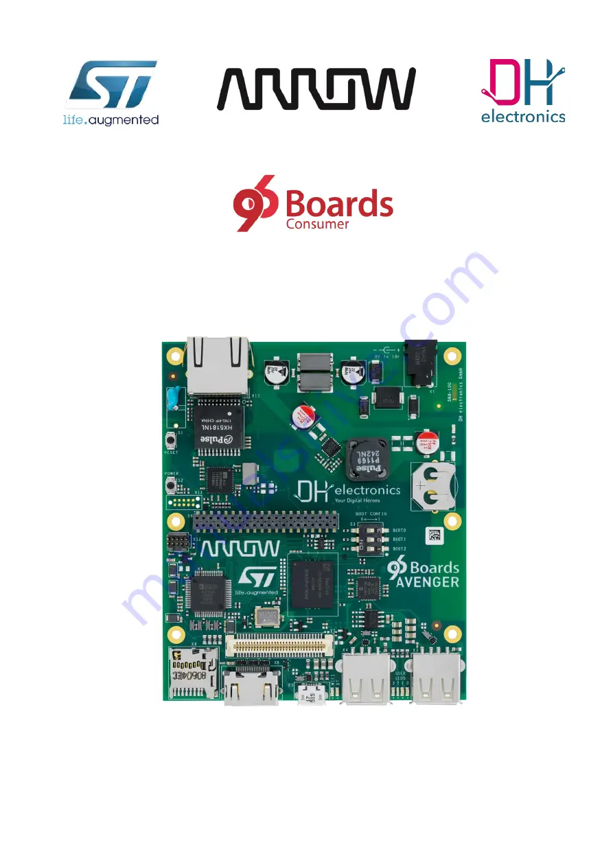
96Boards Avenger96 - Getting Started
DH electronics GmbH
▪
Am Anger 8
83346 Bergen
Germany
YOUR DIGITAL HEROES.
Page 1: ...96Boards Avenger96 Getting Started DH electronics GmbH Am Anger 8 83346 Bergen Germany YOUR DIGITAL HEROES ...
Page 2: ...Page 2 19 History Revision Date Description Change Name R01 13 08 2019 First release based on DOC_Getting Started 588 100_R06_2019 04 12 MH R02 08 10 2019 Added Settings to start glmark2 GPU Demo manually 1 3 5 MH R03 29 05 2020 Updated Link in Chapter 1 3 1 Creating your own image MH ...
Page 3: ...h Speed Expansion Connector 10 1 1 7 JTAG Connectors 11 1 2 Set Up Guide 13 1 2 1 Easy step by step guide 13 1 2 2 Boot Mode 13 1 2 3 Power Supply 14 1 2 4 HDMI Display 14 1 3 Software 15 1 3 1 Creating your own image 15 1 3 2 Configuring ethernet 16 1 3 3 Starting ST GPU Demo 16 1 3 4 Starting glmark2 GPU Demo 17 1 3 5 Starting glmark2 GPU Demo manually 17 1 3 6 Configuring WiFi by Weston desktop...
Page 4: ... Started 588 200 docx Page 4 19 1 Getting Started with the 96Boards Avenger96 This document is designed for the 96Boards Avenger96 FS00009 PCB number 588 200 only The PCB number of the board can be found on the top right corner of the board next to the power jack ...
Page 5: ...uad SPI interface E Prom 128 byte microSD Socket UHS I speed grade v3 01 USB Host 2x type A 2 0 high speed USB OTG 1x type micro AB 2 0 high speed HDMI WXGA 1366x768 60 fps HDMI 1 4 WiFi Bluetooth WiFi 5 GHz 2 4GHz IEEE 802 11a b g n ac Bluetooth v4 2 BR EDR BLE PCB antenna Ethernet 10 100 1000 Mbit s IEEE 802 3 compliant Push Buttons Power and reset Battery Socket CR1216 CR1220 and CR1225 LEDs 4x...
Page 6: ...S 1x GPIO 12x Reset Power Button SYS_DCIN 1 VDC VIO_OUT 1V8 VCC_OUT 5V0 USB Host 1x I2C 2x I 2C PCB Antenna HDMI 1 4 Transmitter Analog ADV7513 RG B SYS_DCIN 8 18 VDC Boot Mode Switches USB eMMC microSD and SPI boot Reset Button Power Button User LEDs 4x WiFi BT LEDs 2x MIPI CSI 2 1x 2 lanes MIPI CSI 2 de serializer ST STMIPID02 TR VCC Inputs USB_HOST VBUS USB_OTG VBUS VCC_IN 5V0 Single supply VCC...
Page 7: ...st 2 USB 2 0 Host 1 User LEDs WiFi and Bluetooth LEDs Battery connector CR1216 CR1220 or CR1225 Power Jack Gigabit Ethernet Reset Button Power Button JTAG Low Speed Expansion Connector High Speed Expansion Connector Boot Switch 8 GB eMMC Power On LED Please note JTAG connector X12 is not populated See Chapter 1 1 7 JTAG Connectors for further information ...
Page 8: ...DH electronics GmbH R03 DOC_Getting Started 588 200 docx Page 8 19 2x 512 MB DDR3L RAM WiFi 5 GHz 2 4 GHz IEEE 802 11a b g n ac Bluetooth v4 2 BR EDR BLE DHCOR STM32MP15x 2 MB Boot Flash PMIC STPMIC1A CPU STM32MP15x PCB Antenna ...
Page 9: ...UART1_RxD Pin 13 Pin 14 SPI0_DOUT MOSI I2C0_SCL Pin 15 Pin 16 PCM_FS I2C0_SDA Pin 17 Pin 18 PCM_CLK I2C1_SCL Pin 19 Pin 20 PCM_DO I2C1_SDA Pin 21 Pin 22 PCM_DI GPIO A Pin 23 Pin 24 GPIO B GPIO C Pin 25 Pin 26 GPIO D GPIO E Pin 27 Pin 28 GPIO F GPIO G Pin 29 Pin 30 GPIO H GPIO I Pin 31 Pin 32 GPIO J GPIO K Pin 33 Pin 34 GPIO L 1V8 Pin 35 Pin 36 SYS_DCIN 5V Pin 37 Pin 38 SYS_DCIN GND Pin 39 Pin 40 G...
Page 10: ...ted DSI_D0 Pin 29 Pin 30 GND GND Pin 31 Pin 32 I2C0_SCL DSI_D1 Pin 33 Pin 34 I2C0_SDA DSI_D1 Pin 35 Pin 36 I2C1_SCL GND Pin 37 Pin 38 I2C1_SDA Not connected Pin 39 Pin 40 GND Not connected Pin 41 Pin 42 Not connected GND Pin 43 Pin 44 Not connected Not connected Pin 45 Pin 46 GND Not connected Pin 47 Pin 48 Not connected GND Pin 49 Pin 50 Not connected USB_D Pin 51 Pin 52 GND USB_D Pin 53 Pin 54 N...
Page 11: ...g Connect TC2050 footprint With this design JTAG can be accessed with a standardized TC2050 IDC NL Cable In order to hold the cable in place there is also an TC2050 CLIP available which locks the cable to the board The Tag Connect footprint is placed on the top side of the Avenger96 as well as on the bottom side This way the connector can be used on either side of the board Pin Net 1 1V8 2 SYS_JTM...
Page 12: ... which uses the standard Cortex 10 pin 0 05 JTAG SWD Connector Pinout The footprint is designed for the Samtec FTSH 105 01 F D K but it is also possible to use other pin headers with the same dimensions like Mouser 855 M50 3500542 Harwin M50 3500542 or similar Pin Net 1 1V8 2 SYS_JTMS SWDIO 3 GND 4 SYS_JTCK SWCLK 5 GND 6 SYS_JTDO SWO 7 Not Connected 8 SYS_JTDI 9 GND 10k Pull down 10 SYS_JTRST ...
Page 13: ...sure the boot switch is set to boot from the NOR Flash See chapter 1 2 2 Connect a display via the HDMI connector Connect keyboard and mouse to the host USB ports Connect a proper power supply See chapter 1 2 3 Plug the power supply into the power socket 1 2 2 Boot Mode The Avenger96 supports multiple boot options which are selected by the DIP switch S3 To select a logical 1 a switch needs to be p...
Page 14: ...d provides a power consumption of up to 24 W In case you just need the connector only you can use a cable like this one https www arrow de products 053 0198r tensility international However the recommended power supply provides 12 V at a maximum output current of 2 A 1 2 4 HDMI Display The Avenger96 supports a resolution up to WXGA 1366 x 768 at a refresh rate of 60 fps Therefore you can connect y...
Page 15: ...nux Weston A Yocto Project Based Distro When Linux starts up the standard Weston desktop will appear on the display A terminal window can be opened by clicking on the terminal icon in the down left corner Known image limitations missing features SAI support MIPI DSI and MIPI CSI are not yet supported HDMI CEC Battery and power button 1 3 1 Creating your own image If you want to create your own Ave...
Page 16: ...s plugged into the RJ45 connector autonegotiation will start automatically and the net work service will try to get IP address over DHCP The progress of network card configuration can be checked by executing ifconfig eth0 When eth0 has already received IP address the network connection can be tested by ping google com 1 3 3 Starting ST GPU Demo ...
Page 17: ...ing command for showing all the options for glmark2 glmark2 es2 wayland h Finally all you have to do is starting it with the desired settings like for instance in windowed mode with anno tation turned on glmark2 es2 wayland size 800x600 annotate For displaying it in full screen use this command glmark2 es2 wayland fullscreen annotate To close glmark2 all you have to do is clicking in the Terminal ...
Page 18: ... last command will list the WiFi hot spots in range If a WiFi network uses WPA authentication the following commands will connect to it cd cp etc wpa_supplicant conf wpa_passphrase SSID passphrase wpa_supplicant conf Please insert the name of the WiFi network and the passphrase in the command above without quotes or the brackets Now connect to the WiFi network wpa_supplicant B Dnl80211 iwlan0 cwpa...
Page 19: ...address of board 1 3 9 Debug UART U Boot and Linux boot logs as well as a standard Linux console is accessible on the debug UART connected to pin 11 and 13 on the low speed expansion connector UART1 see above One can log into the Linux tty console with the help of a USB serial converter like this https www 96boards org product uartserial Any other USB serial converter can be attached to the UART1 ...