


35
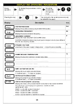
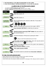
DISPLAY THE OPERATING PARAMETERS
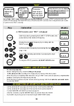
During
operation
To display the parameters on the
display
Scroll the
parameters
through the
keys
Pressing the key
You go back to the system pressure (only
for MASTER inverter)
Display
Description
m.u..
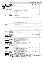
P 3.2
SYSTEM PRESSURE
Displays the system pressure (only for MASTER inverter)
bar
F 45
OPERATING FREQUENCY
Displays the motor revolution Frequency.
Hz
A 6.5
ABSORBED CURRENT
Displays the motor absorbed current (RMS value)
CAUTION! Standard ammeter may read input and output current values different
from the one shown by inverter.
A
V 230
DYNAMIC VOLTAGE
It matches to the power supply ‘voltage value’ - only with pump in standby.
V
PF .85
Power factor (COSFI):
Shows the instantaneous value of the power factor
(only T/T models)
Tm 50
POWER MODULE TEMPERATURE
Displays the inverter’s electronic module temperature.
°C
Ti 30
INVERTER BOX INTERNAL TEMP.
Displays the box internal Temperature
(only T/T models)
°C
Tc 50
INVERTER BOX INTERNAL TEMP.
Displays the box internal Temperature
(only T/T models)
°C
In 0
INPUT ACTIVATION STATUS
Displays the input signal activation Status
1= enabled input / 0= input not enabled
Ou 0
OUTPUT ACTIVATION STATUS
Displays the output relay activation Status
1= enabled input / 0= input not enabled
S1-S2
STATUS RS 485 (SLAVE connection)
Displays the status of the inverter SLAVE connected to the inverter MASTER.
The parameter is not displayed in applications STAND-ALONE
(parameter W = NC).
XX-XX = no SLAVE inverter connected
S1-XX = inverter SLAVE1 connected
XX-S2 = inverter SLAVE2 connected
S1-S2 = inverter SLAVE1 e SLAVE2 connected


