dg_toe10gip_cpu_instruction_xilinx_en.doc
23-Aug-19
Page 36
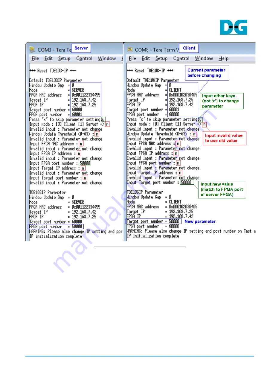
Figure 8-2 Change IP parameter result
Page 1: ...on Setting 12 4 FPGA board setup 13 5 Main menu 19 5 1 Show TCPIP parameters 19 5 2 Reset TCPIP parameters 20 5 3 Send Data Test 22 5 4 Receive Data Test 25 5 5 Full duplex Test 28 Part B TOE10G IP wi...
Page 2: ...one FPGA board transferring data with Test PC More details to run the demo by using FPGA and Test PC are described in PartA Second one Test Env B uses two FPGA boards to transfer data from the 1st FPG...
Page 3: ...connecting between FPGA board and PC 5 mini USB cable ZC706 or micro USB cable ZCU102 KCU105 VCU118 connecting between FPGA board and PC for Serial console 6 tcpdatatest exe and tcp_client_txrx_40G ex...
Page 4: ...dg_toe10gip_cpu_instruction_xilinx_en doc 23 Aug 19 Page 4 Figure 2 1 TOE10G IP with CPU demo FPGA PC on ZC706...
Page 5: ...dg_toe10gip_cpu_instruction_xilinx_en doc 23 Aug 19 Page 5 Figure 2 2 TOE10G IP with CPU demo FPGA PC on ZCU102...
Page 6: ...dg_toe10gip_cpu_instruction_xilinx_en doc 23 Aug 19 Page 6 Figure 2 3 TOE10G IP with CPU demo FPGA PC on KCU105...
Page 7: ...dg_toe10gip_cpu_instruction_xilinx_en doc 23 Aug 19 Page 7 Figure 2 4 TOE10G IP with CPU demo FPGA PC on VCU118...
Page 8: ...hows the example of the network setting 3 1 IP Setting Figure 3 1 Setting IP address for PC 1 Open Local Area Connection Properties of 10 Gb connection as shown in the left window of Figure 3 1 2 Sele...
Page 9: ...2 Set frame size jumbo frame 1 On Local Area Connection Properties window click Configure as shown in Figure 3 2 2 On Advanced Tab select Jumbo Packet Set Value to 9014 Bytes for Jumbo Frame support o...
Page 10: ...dg_toe10gip_cpu_instruction_xilinx_en doc 23 Aug 19 Page 10 3 On Link Speed select 10 Gbps Full Duplex for running 10 Gigabit speed as shown in Figure 3 3 Figure 3 3 Set link speed 10 Gbps...
Page 11: ...ptions and click Properties button 5 On Performance Options window select Low Latency Interrupts and click Properties button 6 On Low Latency Interrupts window select Use Low Latency Interrupts and cl...
Page 12: ...oc 23 Aug 19 Page 12 3 3 Power Option Setting 1 Open Control Panel and select Power Options as shown in the left window of Figure 3 5 2 Change setting to High Performance as shown in the right window...
Page 13: ...d setting on ZC706 board is shown in Figure 4 1 Insert jumper to J17 to enable Tx SFP Set SW11 to configure PS from JTAG Set SW4 to use USB JTAG Figure 4 1 ZC706 board setting b Board setting on ZCU10...
Page 14: ...AG programming 3 Connect micro USB cable ZCU102 KCU105 VCU118 board or mini USB cable ZC706 board from FPGA board to PC for USB UART 4 Connect power supply to FPGA development board 5 Connect 10Gb Eth...
Page 15: ...board 7 Open Serial console When connecting FPGA board to PC many COM ports from FPGA connection are detected and displayed on Device Manager In case of KCU105 VCU118 select Standard COM port In case...
Page 16: ...L shell and change current directory to download folder which includes demo configuration file Type toe10cputest_zcu102 or zc706 bat as shown in Figure 4 7 Figure 4 7 Example command script for downlo...
Page 17: ...ARP request 10 Default parameter in client mode is displayed on the console Figure 4 9 Message after system boot up If Ethernet connection has the problem and the status is linked down the error messa...
Page 18: ...rameters to initialize system as shown in Figure 4 11 If user inputs other keys the menu to change parameter will be displayed The example to change parameter is shown in topic 5 2 Reset TCPIP paramet...
Page 19: ...please input 0 to initialize the IP in client mode 3 FPGA MAC address 48 bit hex value to be MAC address of FPGA Default value is 0x000102030405 4 Target IP IP address of destination device 10 Gb Ethe...
Page 20: ...ameters and the range of each parameter is described as follows 1 Window Update Gap Set threshold value to transmit window update packet Valid value is 0x00 0x3F 0 63 The unit size of threshold value...
Page 21: ...dg_toe10gip_cpu_instruction_xilinx_en doc 23 Aug 19 Page 21 Figure 5 2 Change IP parameter result...
Page 22: ...recommended parameters to run test application on PC will be displayed Next Wait Open connection is displayed to wait the application on PC running 3 On Command prompt input test parameters following...
Page 23: ...dg_toe10gip_cpu_instruction_xilinx_en doc 23 Aug 19 Page 23 Figure 5 3 Send data test by using non jumbo frame Figure 5 4 Send data test by using jumbo frame...
Page 24: ...e input is invalid Out of range input or Invalid input will be displayed After that the operation is cancelled as shown in Figure 5 5 Figure 5 7 Figure 5 5 Error from invalid transfer size Figure 5 6...
Page 25: ...nput c to run Test PC as a client b Dir Input t to run Test PC for sending test data to FPGA c Server IP Input same value as IP address of FPGA d Server port Input same value as port number of FPGA e...
Page 26: ...dg_toe10gip_cpu_instruction_xilinx_en doc 23 Aug 19 Page 26 Figure 5 8 Receive data test without data verification Figure 5 9 Receive data test when enable data verification...
Page 27: ...dg_toe10gip_cpu_instruction_xilinx_en doc 23 Aug 19 Page 27 Figure 5 10 Receive data test when data verification is failed...
Page 28: ...n on PC will be displayed Next Wait Open connection is displayed to wait application on PC running 3 On Command prompt input test parameters following the recommended value There are four parameters f...
Page 29: ...dg_toe10gip_cpu_instruction_xilinx_en doc 23 Aug 19 Page 29 Figure 5 11 Full duplex test without data verification Figure 5 12 Full duplex test with data verification...
Page 30: ...P copper cable DAC or 2x10 Gb SFP transceiver 10G BASE R with optical cable for network connection between two FPGA boards Note When running on VCU118 QSFP transceiver is used instead 3 micro USB cabl...
Page 31: ...dg_toe10gip_cpu_instruction_xilinx_en doc 23 Aug 19 Page 31 Figure 6 1 TOE10G IP with CPU demo FPGA FPGA by ZC706 and ZCU102...
Page 32: ...he step after FPGA configuration is described as follows 1 Open Serial console for board 1 and board 2 In this document COM3 is Serial console for FPGA board 1 which is set to server mode and COM8 is...
Page 33: ...al console before client Serial console Server must be reset to wait ARP packet sent by client when running initialization After finishing parameter setting and reset process IP starts initialization...
Page 34: ...and 1 for server 3 FPGA MAC address 48 bit hex value to be MAC address of FPGA Default value is 0x000102030405 client mode or 0x001122334455 server mode 4 Target IP IP address of destination device t...
Page 35: ...server must be matched i e a Target IP of server FPGA IP of client b FPGA IP of server Target IP of client c Target port number of server FPGA port number of client d FPGA port number of server Target...
Page 36: ...dg_toe10gip_cpu_instruction_xilinx_en doc 23 Aug 19 Page 36 Figure 8 2 Change IP parameter result...
Page 37: ...e input must be aligned to 8 The input is decimal unit when user inputs only digit number User can add 0x to be a prefix when the input is hexadecimal unit This value must be equal to transfer size on...
Page 38: ...dg_toe10gip_cpu_instruction_xilinx_en doc 23 Aug 19 Page 38 Figure 8 3 Send data test by using non jumbo frame Figure 8 4 Send data test by using jumbo frame...
Page 39: ...If inputs are valid Wait Open connection will be displayed 3 On Serial console of client input three test parameters in send data test a Input transfer size Unit of transfer size is byte Valid value i...
Page 40: ...dg_toe10gip_cpu_instruction_xilinx_en doc 23 Aug 19 Page 40 Figure 8 5 Receive data test with data verification...
Page 41: ...displayed 3 On Serial console of client input four test parameters in full duplex test a Input transfer size Unit of transfer size is byte Valid value is 0x8 0x7_FFFF_FFF8 The input must be aligned t...
Page 42: ...doc 23 Aug 19 Page 42 Figure 8 6 shows full duplex test The left window is Serial console from FPGA running as server and the right window is Serial console from FPGA running as client Figure 8 6 Ful...
Page 43: ...3 Aug 19 Page 43 9 Revision History Revision Date Description 1 0 17 Jan 18 Initial version release 1 1 4 Apr 18 Add Part B FPGA FPGA test 1 2 26 Feb 19 Add KCU105 board and change software to tcp_cli...