background image

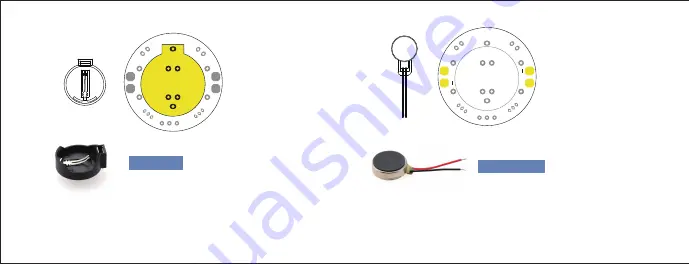
The battery clip is for holding the coin cell battery. Set the battery 
clip on the white footprint of the upper side of the board. Solder the 
two clip legs from the opposite side while keeping the part flat.

5. Solder the 
Battery Clip

Battery Clip

4-Soldering Light

Chaser Kit V1

The vibration motor provides the power source that enables Mr. NEON 
to happily hum along. Solder the motors into the front of the board. 
The red leg goes into the hole labeled “+”.

6. Solder the 
vibration motors

After soldering, cut off 
the remaining length of 
the wire.

4-Soldering Light

Chaser Kit V1

+

+

Vibration Motor

Summary of Contents for Light Chaser

Page 1: ...Light Chaser Beginner Soldering Kit ...

Page 2: ...g monster whose eyes or tentacles glow and dim depending on surrounding light The stronger the light is the faster Mr NEON moves There is no programming involved and all of the soldering is beginner friendly making it perfect for budding electronic enthusiasts Mr NEON is also able to change faces through expression stickers Product Introduction Compoents Introduction Coin Cell Battery Vibration Mo...

Page 3: ...ince strobe A controls water flow through the thick pipe water flow will increase when strobe A opens This is the function of the transistor 4 The water flow in the thick pipe determines the speed of the water wheel increased water flow will make the waterwheel spin faster The pool represents the coin cell battery the waterwheel represents the vibration motor strobe B represents the photodiode Str...

Page 4: ...the soldering iron s sweet spot shown in diagram and make sure it touches both the leg and the metal ring Hold for 1 to 2 seconds Your solder joints should look like this a tiny volcano How to Solder Pull the soldering wire away first then the soldering iron Step3 Step4 Step1 Step2 ...

Page 5: ...ts Just solder the resistors to its proper position on the board shown in the diagram regardless of the electrode being positive or negative 1 Solder the resistors After soldering cut off the remaining length of the wire 20K 20K 20K 20K Components Soldering Sequence 20K Ohm Resistor Step5 Step6 WARNING Please wear safety goggles This kit requires soldering and clipping leads Making the head ...

Page 6: ... white print on the board resembles a half circle Make sure that place the transistors in the holes on the basis of the silkscreen The round side on the board should match the round side of the transistor Transistor 2 Solder the switch After soldering cut off the remaining length of the wire 3 Solder the transistors After soldering cut off the remaining length of the wire ...

Page 7: ...ntensity and can be used to change a circuit s current Insert the photodiodes into the front of the board Each photodiode has a short leg and a long leg The long leg goes into the hole labeled with a long line Place the photodiode into the front side of the board Then bend the photodiode into a 90 degree angle see picture making sure to leave around 25mm at the base of the diode Flip the board ove...

Page 8: ...the part flat 5 Solder the Battery Clip Battery Clip 4 Soldering Light Chaser Kit V1 The vibration motor provides the power source that enables Mr NEON to happily hum along Solder the motors into the front of the board The red leg goes into the hole labeled 6 Solder the vibration motors After soldering cut off the remaining length of the wire 4 Soldering Light Chaser Kit V1 Vibration Motor ...

Page 9: ...Take out the plastic paper and the sticker with a printed triangle Step1 Making the Base Mr Neon should at this point look like the above picture ...

Page 10: ...Unpeel the triangle sticker and place it atop the plastic paper Step2 Cut the plastic paper with a scissor along the edge of the triangle Step3 ...

Page 11: ...Bend three small triangles into 90 degrees along dotted lines Step5 Trim the sharp corners of the triangle Step4 ...

Page 12: ...otors against Mr NEON s legs Step8 Place the plastic tubing over the photodiodes this prevents electric interference with the exposed probe Step9 Place the adhesive against the body as shown Step6 Put the head on the body Step7 ...

Page 13: ... Sticker Base Sticker Face Sticker x1 x1 x1 x1 x2 x2 x2 x4 x1 x1 x1 x1 x1 Shipping List You ve assembled Mr Neon You can add stickers to Mr Neon to give him appearance and flair that make him stand out from the rest A step by step video walkthrough showing the assembly of Mr Neon is available online to view it please go to the DFRobot Mr Neon product page ...

Page 14: ...dfrobotcn dfrobot dfrobot www DFRobot com Made in China Designed by ...

Reviews: