background image

Connect four motor wires to Motor Terminal. And apply power through motor power terminal
(Figure 4).

(/wiki/index.php/File:RomeoSample.png)

Fig3: Romeo Motor Connection Diagram

Pin Allocation

"PWM Mode"

Pin

Function

Digital 4

Motor 1 Direction control

Digital 5

Motor 1 PWM control

Digital 6

Motor 2 PWM control

Digital 7

Motor 2 Direction control

"PLL Mode"

Pin

Function

Digital 4

Motor 1 Enable control

Digital 5

Motor 1 Direction control

Digital 6

Motor 2 Direction control

Digital 7

Motor 2 Enable control

PWM Control Mode

(/wiki/index.php/File:RomeoMotorJmp.png)

Fig4: PWM Motor
Control Pin
Allocation

Summary of Contents for DFR0004

Page 1: ...rom Arduino open source platform it is supported by thousands of open source codes and can be easily expanded with most Arduino Shields The integrated 2 way DC motor driver and wireless socket gives a...

Page 2: ...t Terminal 6v to12v One Unregulated Servo Power Input Terminal you supply regulated 4v to 7 2v One Servo input power selection jumper One Serial Interface Module Header for APC220 Bluetooth Module Two...

Page 3: ...ogrammed by Arduino IDE 0022 and above It can be downloaded at Arduino cc http arduino cc en Main Software Please select Arduino UNO as the hardware Romeo Configuration Servo Power Select Jumper As mo...

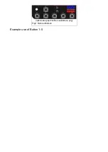
Page 4: ...wiki index php File RomeoButtons png Fig2 Romeo Buttons Example use of Button 1 5...

Page 5: ...from the sensor digitalWrite 13 HIGH get the key key get_key adc_key_in convert into key press if key oldkey if keypress is detected delay 50 wait for debounce time adc_key_in analogRead 7 read the va...

Page 6: ...n Function Digital 4 Motor 1 Direction control Digital 5 Motor 1 PWM control Digital 6 Motor 2 PWM control Digital 7 Motor 2 Direction control PLL Mode Pin Function Digital 4 Motor 1 Enable control Di...

Page 7: ...e Figure 5 Pin 4 7 7 8 for old Romeo version are motor direction control pins Pin 5 6 6 9 for old Romeo version are motor speed control pins For previous Romeo board the pins used to control the motor...

Page 8: ...HIGH void back_off char a char b Move backward analogWrite E1 a digitalWrite M1 LOW analogWrite E2 b digitalWrite M2 LOW void turn_L char a char b Turn Left analogWrite E1 a digitalWrite M1 LOW analo...

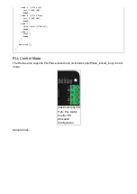
Page 9: ...eak case z Serial println Hello break case x stop break else stop PLL Control Mode The Romeo also supports PLLPhase locked loop wiki index php Phase_locked_loop control mode wiki index php File Romeov...

Page 10: ...e m1p byte m2p Drive Motor Power Mode digitalWrite E1 HIGH analogWrite M1 m1p digitalWrite E2 HIGH analogWrite M2 m2p void setup void int i for i 6 i 9 i pinMode i OUTPUT Serial begin 19200 Set Baud R...

Page 11: ...cial Categories Product Manual wiki index php Category Product_Manual DFR Series wiki index php Category DFR_Series Motor Controllers wiki index php Category Motor_Controllers MicroControllers wiki in...

Reviews: