background image

Applying Power

This is one of the most important steps in getting the Romeo up and communicating with your
host controller. You MUST make sure that you apply power to the Power Terminal using the
correct polarity. Reverse Polarity will damage the Romeo. We are not responsible for such
damage, nor do we warranty against such damage.
 Make sure you take time to apply power
correctly. Otherwise, it could get costly for you!

Power from USB: Simply plug USB cable, and the Romeo is able to work. Please notice that
the USB can only supply 500 mA current. It should be able to meet the most requirements for
LED lit application. However it is not enough to power DC motors or servo.

Power from Motor Power Input: Simply connect the ground wire from your supply to the
screw terminal labeled “GND”, and then connect the positive wire from your supply to the screw
terminal labeled “VIN".

NOTE: Maximum supply voltage cannot exceed 14V DC.

Software

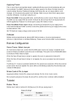
RoMeo can be programmed by Arduino IDE 0022 and above. It can be downloaded at
Arduino.cc (http://arduino.cc/en/Main/Software), Please select “Arduino UNO” as the hardware.

Romeo Configuration

Servo Power Select Jumper

As most servos draw more current than the USB power source can supply. A separate servo
power terminal is provided to power the servo individually. This option can be Enabled/Disabled
by the Servo Power Select Jumper.

When the Servo Power Select Jumper is applied, the servo is powered by internal 5V.

When the Servo Power Select Jumper is not applied, the servo is powered by external power
source.

The Romeo V1.0 uses an automatic switcher for the power source selection. When the external
power source has been applied, the servo will be automatically powered by the external power
instead of USB power.

Motor Control Pin Jumper

Applying the Motor Control Pin Jumpers will allocate Pin 5,6,7,8 for motor control.

Removing the jumpers will release the above Pins, and the motor controller will be disabled.

Tutorial

Button Press

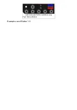
RoMeo has 5 build in buttons S1­S5 (Figure 2). S1­S5 use analog input 7,

"Button Pin Map"

Pin

Function

Analog Pin 7

Button S1­S5

Summary of Contents for DFR0004

Page 1: ...rom Arduino open source platform it is supported by thousands of open source codes and can be easily expanded with most Arduino Shields The integrated 2 way DC motor driver and wireless socket gives a...

Page 2: ...t Terminal 6v to12v One Unregulated Servo Power Input Terminal you supply regulated 4v to 7 2v One Servo input power selection jumper One Serial Interface Module Header for APC220 Bluetooth Module Two...

Page 3: ...ogrammed by Arduino IDE 0022 and above It can be downloaded at Arduino cc http arduino cc en Main Software Please select Arduino UNO as the hardware Romeo Configuration Servo Power Select Jumper As mo...

Page 4: ...wiki index php File RomeoButtons png Fig2 Romeo Buttons Example use of Button 1 5...

Page 5: ...from the sensor digitalWrite 13 HIGH get the key key get_key adc_key_in convert into key press if key oldkey if keypress is detected delay 50 wait for debounce time adc_key_in analogRead 7 read the va...

Page 6: ...n Function Digital 4 Motor 1 Direction control Digital 5 Motor 1 PWM control Digital 6 Motor 2 PWM control Digital 7 Motor 2 Direction control PLL Mode Pin Function Digital 4 Motor 1 Enable control Di...

Page 7: ...e Figure 5 Pin 4 7 7 8 for old Romeo version are motor direction control pins Pin 5 6 6 9 for old Romeo version are motor speed control pins For previous Romeo board the pins used to control the motor...

Page 8: ...HIGH void back_off char a char b Move backward analogWrite E1 a digitalWrite M1 LOW analogWrite E2 b digitalWrite M2 LOW void turn_L char a char b Turn Left analogWrite E1 a digitalWrite M1 LOW analo...

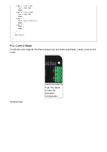
Page 9: ...eak case z Serial println Hello break case x stop break else stop PLL Control Mode The Romeo also supports PLLPhase locked loop wiki index php Phase_locked_loop control mode wiki index php File Romeov...

Page 10: ...e m1p byte m2p Drive Motor Power Mode digitalWrite E1 HIGH analogWrite M1 m1p digitalWrite E2 HIGH analogWrite M2 m2p void setup void int i for i 6 i 9 i pinMode i OUTPUT Serial begin 19200 Set Baud R...

Page 11: ...cial Categories Product Manual wiki index php Category Product_Manual DFR Series wiki index php Category DFR_Series Motor Controllers wiki index php Category Motor_Controllers MicroControllers wiki in...

Reviews: