DFI WM343-SD Series Installation Manual Download Page 13

13

www.dfi .com

 A47300735

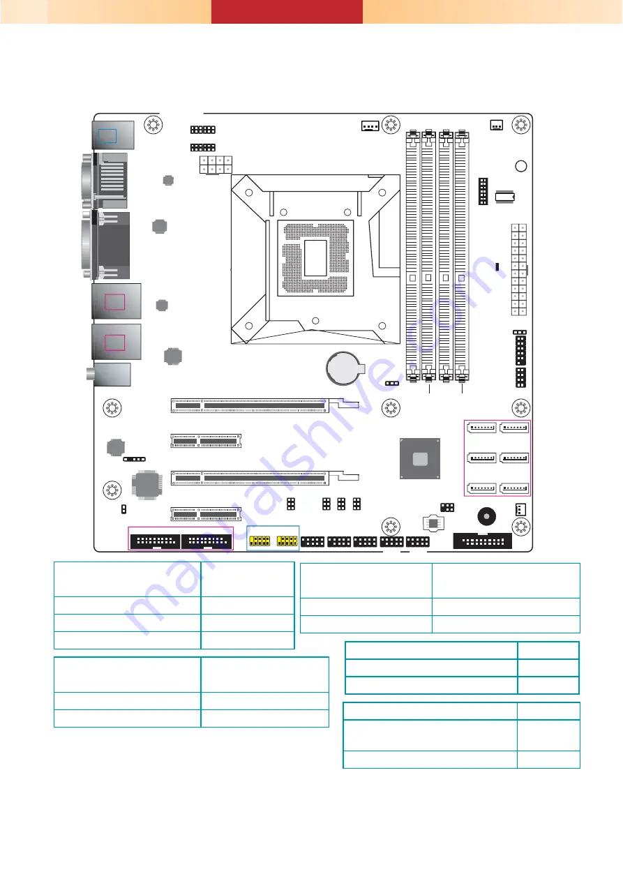
WM343-SD331 (C236/Q170)

COM 2 RS232/422/485

Select (JP13)

COM 2 RS232/Power

Select (JP14)

COM 2 RS232/422/485

Select (JP11)

COM 2 RS232/422/485

Select (JP12)

COM 1 RS232/422/485

Select (JP8)

COM 1

RS232/422/485

Select (JP10)

COM 1

RS232/422/485

Select (JP7)

Intel

Q170

1

2

5

6

SMBus

+12V

Power

1

5

4

8

PCIe 2 (PCIe x4) 

PCIe 4 (PCIe x4) 

Standby

Power LED

PCIe 1 (PCIe x16 or PCIe x8)

PCIe 3 (PCIe x8)

1

ATX

Power

12

24

13

1

2

11

12

Front

Panel

1

2

LAN LED

7

8

PS/2 KB/MS

USB 6

USB 5

USB 2.0

DVI-D

DP++

LAN 1

USB 2

USB 1

USB 3.0

LAN 2

USB 4

USB 3

USB 3.0

Line-out

Mic-in

Socket LGA1151

2 1

13

14

LPC

TPM

(optional)

USB 3.0

Battery

Buzzer

Chassis

Intrusion

1

SPI Flash

BIOS

1

1

1

1

1

1

SATA 1

SATA 3

SATA 5

SATA 0

SATA 2

SATA 4

SATA 3.0

1

S/PDIF

1

Clear CMOS

Data (JP1)

DDR4_1

DDR4_3

DDR4_4

DDR4_2

System Fan 2

1

Auto Power-on

Select (JP5)

1

CPU Fan

1

System Fan 1

1

1

2

19

DIO

1

2

10

9

1

2

10

9

1

2

10

9

1

2

10

9

1

2

10

9

COM 5

COM 2

COM 6

COM 3

COM 4

1

2

10

9


USB 7-8

USB 2.0

1

2

5

6

1

2

5

6

1

2

5

6

1

2

5

6

5

1

6

2

5

1

6

2

5

1

6

2

5

1

6

2

COM 1

VGA

11

10

1

11

10

1

COM 1 RS232/Power

Select (JP9)


USB 5-6


USB 7-8

Nuvoton

NCT6106D

Realtek

ALC888

Intel 

WGI219LM

Intel 

WGI210AT

ASMedia

ASM1442

Chrontel

CH7517A

1

2

10

9


USB 9-10

Clear CMOS Data

JP1

Normal (default)             

1-2 On

Clear CMOS Data

2-3 On

Notes: 
1. When COM 1 RS232/422/485 is selected,
   JP8 and JP10 must be set in accordance to JP7.
2. When COM 2 RS232/422/485 is selected, 

   JP12 and JP13 must be set in accordance to JP11.

RS232/422/485 Select JP7 (COM 1)

JP11 (COM 2)

RS232 (default)             

1-2 On

RS422 Full Duplex

3-4 On

RS485

5-6 On

RS232/Power Select

JP9 (COM 1) 
JP14 (COM 2)

RS232  (default)                1-3  (RI),  2-4  (DCD)  On
RS232 with power

3-5 (+5V), 4-6 (+12V) On

Auto Power-on Select

JP5

Power-on via power button 

(default)             

1-2 On

Power-on via AC power

2-3 On

RS232/422/485 Select JP8/JP10 (COM 1)

JP12/JP13 (COM 2)

RS232 (default)             

1-3, 2-4 On

RS422 Full Duplex/RS485

3-5, 4-6 On

Summary of Contents for WM343-SD Series

Page 1: ...ew DFI reserves the right to change the specifications at any time prior to the product s release For the latest revision and for a more details of the installation process please refer to the user s...

Page 2: ...delines and follow the procedure to open the system 1 Make sure the system and all other peripheral devices connected to it have been powered off 2 Disconnect all power cords and cables 3 Remove the t...

Page 3: ...3 Installing a DIMM To access the DIMM sockets first remove the CD tray by uninstalling the screws from the rear panel and inside the chassis CD tray screw CD tray screw...

Page 4: ...ss down on the DIMM until the release tabs spring back to secure the DIMM in place The installed DIMM Notes 1 The WM343 SD330 is equipped with two or four DDR4 dual channel sockets depending on the ch...

Page 5: ...ssis and remove the drive bay Thumb screw 3 5 SATA Drive 2 Secure the hard drive to the drive bay Align the mounting holes on the SATA drive with the mounting holes on the HDD drive bay Use 4 mounting...

Page 6: ...cable to the connectors on the SATA drive And connect the other end of the SATA data cable on the motherboard 2 5 SATA Drive Use the same HDD drive bay to secure a 2 5 hard disk to the system Refer t...

Page 7: ...the optical bay in the system Use the following procedure to install a second and third 2 5 HDD SSD 1 Attach 4 standoffs to the 2 5 HDD or SSD Mounting screw Mounting screw 2 Secure the hard drive to...

Page 8: ...y back to the system 4 Connect the SATA data cable and power cable to the connectors on the SATA drive And connect the other end of the SATA data cable on the motherboard SATA data and power cable SAT...

Page 9: ...Use the following procedure to install a PCIe expansion card 1 Remove the mounting screws to uninstall the card slot bracket 2 Insert the expansion card in the connector on the motherboard and press...

Page 10: ...Reinstall the card slot bracket to secure the expansion card in place Notes 1 The WM343 SD330 is equipped with one PCIe x16 one PCIe x4 and two PCI slots 2 The WM343 SD331 is equipped with two PCIe x...

Page 11: ...and align the notch in the connector of the PCIe card with the notch in the connector on the system board 2 Push the Mini PCIe card down and use the provided mounting screws to secure the card on the...

Page 12: ...verter Power Select JP4 Backlight Power Select JP3 Panel Power Select JP2 Mini PCIe mSATA Signal Select JP6 NXP PTN3460 1 System Fan 2 SPI Flash BIOS Line out Mic in LAN 1 USB 2 USB 1 USB 3 0 LAN 2 US...

Page 13: ...an 1 System Fan 1 1 1 2 19 DIO 1 2 10 9 1 2 10 9 1 2 10 9 1 2 10 9 1 2 10 9 COM 5 COM 2 COM 6 COM 3 COM 4 1 2 10 9 USB 7 8 USB 2 0 1 2 5 6 1 2 5 6 1 2 5 6 1 2 5 6 5 1 6 2 5 1 6 2 5 1 6 2 5 1 6 2 COM 1...

Reviews: