


User's Manual | MDPi Series
14
Electromagnetic immunity
The monitor is intended for use in the electromagnetic environment specified below. The cus-
tomer or the user of the monitor should assure that it is used in such an environment.
Immunity test
IEC 60601
Test levels
Compliance level
Electromagnetic envi-
ronment – guidance
Electrostatic
discharge
(ESD)
IEC 61000-4-2
± 8kV contact
± 15kV air
± 8kV contact
± 15kV air
Floors should be wood,
concrete or ceramic
tile. If floors are cov
-
ered with synthetic
material, the relative
humidity should be at
least 30%
Electrical fast
transient/burst
IEC 61000-4-4
± 2kV for power supply
lines
± 1kV for input/ output
lines
± 2kV for power supply lines
± 1kV for input/ output lines
Mains power qual-
ity should be that of a
typical commercial or
hospital
environment
Surge
IEC61000-4-5 ± 1 kV line(s) to line(s)
± 2 kV line(s) to earth
± 1 kV line(s) to line(s)
± 2 kV line(s) to earth
Mains power qual-
ity should be that of a
typical commercial or
hospital
environment
Voltage dips,
short
interruptions
and voltage
variations on
power supply
input
lines
IEC 61000-4-
11
0% residual voltage for
0.5 cycle.
0% residual voltage for
1 cycle.
70% residual voltage
for 0.5s.
0% residual voltage for
5s.
0% residual voltage
for 0.5 cycle.
0% residual voltage
for 1 cycle.
70% residual voltage for 0.5s.
0% residual voltage for 5s.
Mains power qual-
ity should by that of a
typical commercial or
hospital
environment. If the user
of the monitor requires
continued operation
during power mains
interruptions, it is
recommended that the
monitor be powered
from an uninterruptible
power supply or a bat-
tery.
Power fre-
quency (50/60
Hz) mag-
netic field IEC
61000-4-8
30 A/m
Not applicable
Power frequency mag-
netic fields should be
at levels characteristic
of a typical location in
a typical commercial or
hospital environment.
Chapter 3
Cleaning the display
User's Manual | MDPi Series
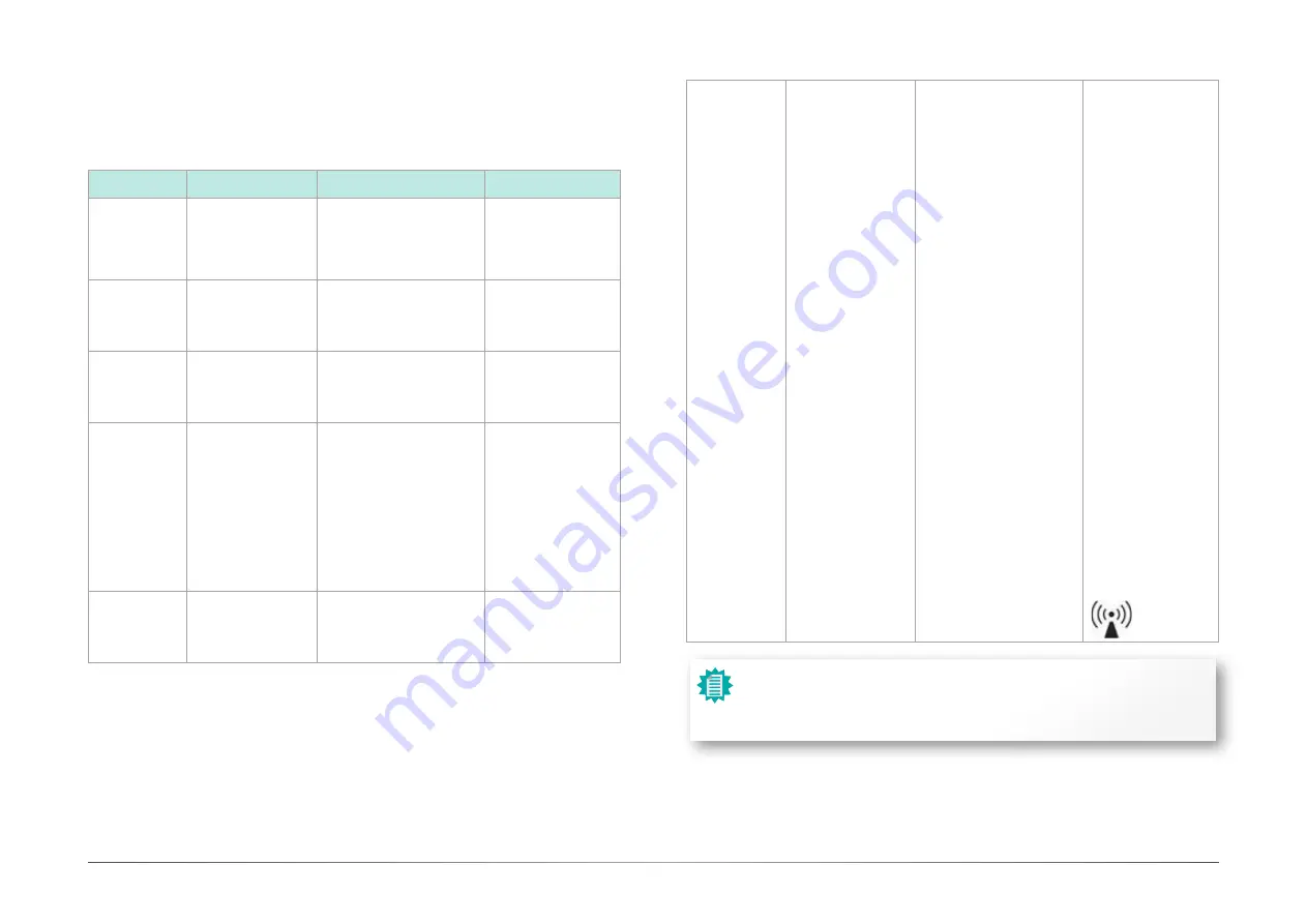
Conducted RF
IEC 61000-4-6
Radiated RF
IEC 61000-4-3
3 V at 0,15 - 80MHz
6 V at ISM bands
10 V/m at 80-2,
700MHz.
And 9-28V/m at 385-
6,000MHz, Pulse
Mode: 27 V/m at
385MHz
28 V/m at 450MHz
9V/m at
710/745/780MHz
28 V/m at
810/870/930MHz
28 V/m at
1720/1845/1970MHz
28 V/m at
2450MHz 9V/m at
5240/5500/5785MHz
3 V at 0,15 - 80MHz
6 V at ISM bands
10V/m at 80-2,700MHz.
And 9-28V/m at 385-
6,000MHz, Pulse Mode: 27 V/
m at 385MHz
28 V/m at 450MHz
9V/m at 710/745/780MHz
28 V/m at 810/870/930MHz
28 V/m at
1720/1845/1970MHz
28 V/m at 2450MHz 9V/m at
5240/5500/5785MHz
Portable and mobile
RF communications
equipment should be
used no closer to any
part of the monitor,
including cables, than
the recommend
separation distance
calculated from the
equation applicable
to the frequency
of the transmitter.
Recommended
separation distance
d = 1.2√P
d = 1.2√P 80 MHz to
800
MHz
d = 2.3√P 800 MHz to
2.5
Ghz
Where P is the
maximum output
power rating of the
transmitter in watts (W)
according to
the transmitter
manufacturer and d
is the recommended
separation
distance in meters (m).
Field strengths from
fixed RF transmitters,
as
determined by an
electromagnetic site
survey,5 should be less
than the compliance
level in each frequency
range.6
Interference may
occur in the vicinity of
equipment marked with
symbol:
Note:
At 80 MHz and 800 MHz, the higher frequency range applies.
These guidelines may not apply in all situations. Electromagnetic propagation is
affected by absorption and reflection from structures, objects, and people.


