


www.dfi .com
23
Chapter 4 Mounting Options
Panel Mount
The panel mounting kit includes the following:
•
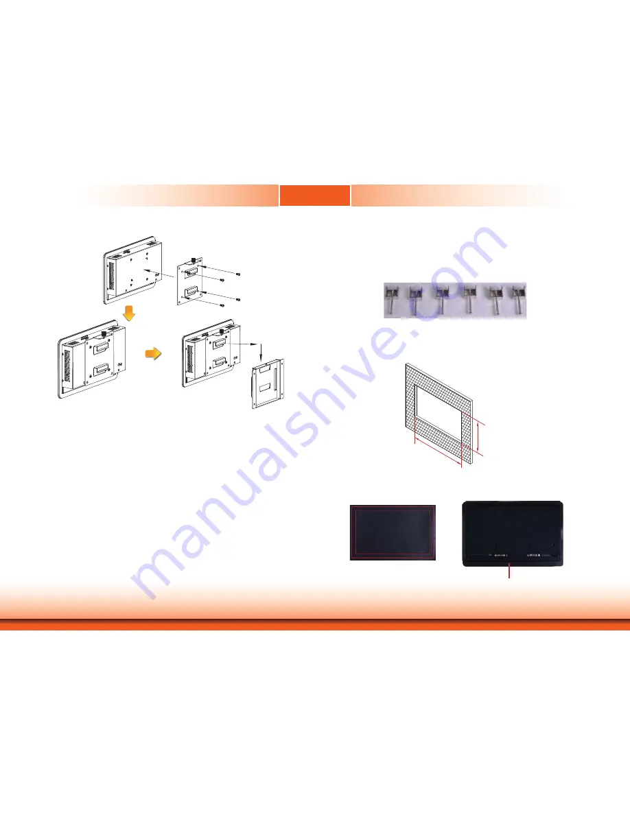
6 mounting clamps
1. Select a place on the panel where you will mount the Panel PC.
2. Cut out a shape on the panel that corresponds to the Panel PC’s rear dimensions
(217.6mm x 128.6mm).
128.60
217
.60
3. Stick the poron foam on the rear panel.
Poron foam
Poron foam


