background image

28

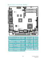
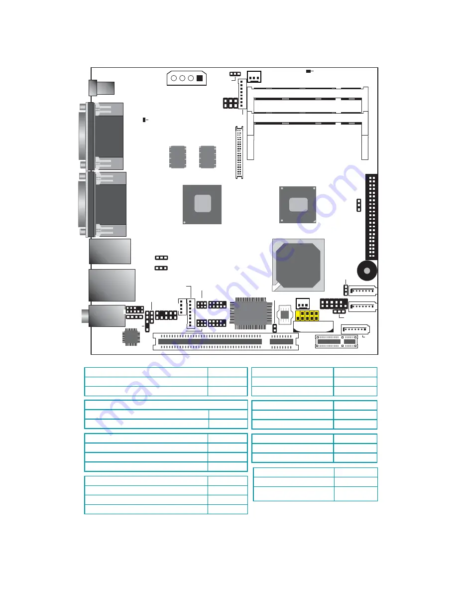
Board Layout and Jumper Settings

Clear CMOS Data

JP8

       Normal (default)

1-2 On

       Clear CMOS Data

2-3 On

PS/2 Power

JP2

          5V (default)

1-2 On

          5V_standby

2-3 On

Panel Power Select

J10

                   +12V             

1-2 On

                   +5V

3-4 On

                   +3.3V (default)

5-6 On

USB Power: 0-1 (JP4), 2-5 (JP3), 6-7 (JP7) 

                       5V (default)

1-2 On

                       5V_standby

2-3 On

Power-on Select

JP6

            Power-on  via  power  button  (default)             

1-2  On

      Power-on via AC power

2-3 On

COM 2 RS232/RS422/RS485 Select

JP5

                  RS232 (default)             

1-2 On

                  RS422

3-4 On

                  RS485 Half Duplex

5-6 On

COM 1 RS232/Power

J7

        RS232 (default)

1-3, 2-4 On

        RS232 with power

3-5 (12V), 4-6 

(5V) On

CF Card Setting

JP9

          Master (default)

1-2 On

          Slave

2-3 On

VGA

HDMI

USB 2-5

LAN

USB 0-1

Mic-in
Line-in
Line-out

1

Power-on

select (J

)

P6

PCIE x1

1

SATA 2

DC-in

12V

1

Front audio

1

1

1

Peripheral power

1

1

SATA 1

SATA 0

1

2

9

10

USB 6-7

Battery

1

Realtek

ALC262

1

1

SPI

1

1

2

5

6

Panel power

select (

)

J10

Intel

ICH8M

LVDS LCD

panel

40

39

2

1

Front panel

1

DIO

1

1

1

IDE

1

KB/Mouse

1

CD-in

COM 1

COM 2

1

DRAM Power
LED

DVI-I
DVI-I

USB 6-7 power
select (J 7

P )

Clear CMOS

(J 8)

P

PS/2 power
select (J 2)

P

S/PDIF

PCI

Chrome 435

1

T

o

p

DVI

-I

port

is

shared

wi

th

HDMI

DDR2_1 SODIMM

DDR2_2 SODIMM

LCD/Inverter power

S3

Atom

Intel

1

USB 2-5 power
select (J

)

P3

USB 0-1 power
select (J

)

P4

1

DIO

power

COM1 RS232/Power
select (J7)

COM2 RS232/

485 select (

)

422/

JP5

2

9

10

1

2

9

10

1

2

5

6

1

2

5

6

43 44

2

Winbond

W83627DHG-P

Chassis

intrusion

2

CF card

setting (J

)

P9

Standby
Power LED

CPU fan

1

1

System fan

DDR2

32Mx16

DDR2

32Mx16

934-ES1210-000G 

A16602130

Summary of Contents for ES121-LRD410

Page 1: ...ount kit 1 VESA bracket 6 bracket screws 1 x Wallmount kit 2 wallmount brackets 4 bracket screws 1 x Rackmount kit 2 L shape rackmount brackets with handle 8 bracket screws 1 Riser card kit X100 4PE1...

Page 2: ...LINE OUT RESET POWER COM 1 ES121 LR Processor Intel AtomTM D510 D410 N450 Chipset Intel ICH8M LAN 1 LAN port COM 1 RS232 422 485 COM2 port 1 RS232 COM1 port Multiple Displays VGA Bottom DVI I Top DVI...

Page 3: ...devices connected to it has been powered off 2 Disconnect all power cords and cables 3 The 6 mounting screws on the sides of the system are used to secure the cover to the chassis Remove these screws...

Page 4: ...ng the mounting screws lift the cover up Lift the Cover Upward 5 The SODIMM sockets SATA drive bay and expansion slots are readily accessible after removing the chassis cover SODIMM sockets SATA drive...

Page 5: ...5 Installing a SODIMM 1 Locate the SODIMM socket on the system board SODIMM sockets 2 Note the key on the socket The key ensures the module can be plugged into the socket in only one direction...

Page 6: ...nd of the module until it slips down into the socket The contact fingers on the edge of the module will almost completely disappear inside the socket SODIMM 4 Push the module down until the clips at e...

Page 7: ...that secure the HDD brackets to the drive bay Mounting screw 2 Align the mounting holes of the SATA drive with the mounting holes on the HDD bracket and then use the provided mounting screws to secure...

Page 8: ...nto the chassis Replace the 4 mounting screws you removed in step 1 Mounting screw SATA power cable SATA data cable 4 Connect the SATA data cable and SATA power cable to the connectors on the SATA dri...

Page 9: ...Mini PCI and Mini PCIe Expansion 1 The riser card kit in the package includes the X100 4PE1 and X100 5PE1 riser cards X100 4PE1 X100 5PE1 2 The PCI and PCIe x1 slots on the system board are used to in...

Page 10: ...into the PCI and PCIe x1 slots that are on the X100 4PE1 riser card The X100 5PE1 riser card is equipped with a Mini PCI slot and a Mini PCIe x1 slot The Mini PCIe x1 slot supports full length or hal...

Page 11: ...11 DC In Used to plug a 12V DC power adapter This jack provides maximum of 60W power and is considered a low power solution Ground Ground 12V 12V...

Page 12: ...2 Wallmount brackets 4 bracket screws Mounting Options 1 At the bottom side of the system use the provided mounting screws to secure the wallmount brackets on each side of the system Mounting screw Wa...

Page 13: ...kmount Mounting kit includes the following 2 L shape rackmount brackets with handle 8 bracket screws Rackmount Mounting 1 The 4 mounting holes on the sides of the system are used to mount the rack mou...

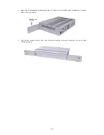
Page 14: ...Use the provided mounting screws to secure the rackmount brackets on each side of the system 3 The photo below shows the rackmount brackets properly installed on each side of the system Rackmount bra...

Page 15: ...the system is not compromised Mechanical Loading Mounting the system in the rack should be such that it will not cause hazard from uneven mechanical loading Circuit Overloading Considerations should b...

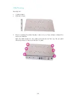
Page 16: ...screws VESA Mounting 1 Prior to installing the VESA bracket make sure you have already installed the wallmount brackets Align the VESA bracket to the wallmount brackets and then use the provided mount...

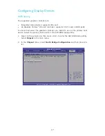
Page 17: ...m and then press Del to enter the AMI BIOS Setup utility Select Chipset in the main menu 2 In the Chipset menu select North Bridge Configuration and then press En ter Configure North Bridge features B...

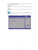
Page 18: ...er to use as the primary boot device BIOS SETUP UTILITY v02 61 C Copyright 1985 2006 American Megatrends Inc Select Screen Select Item Change Option F1 General Help F10 Save and Exit ESC Exit North Br...

Page 19: ...top DVI bottom DVI or HDMI bottom DVI DO NOT connect devices to the top DVI and HDMI at the same time The display will appear blank if ever devices are connected to these ports In a BIOS environment w...

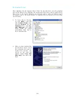
Page 20: ...pear next to the audio devices It indicates that the devices are not config ured correctly 1 To open Device Manag er click Start and then click Control Panel Dou ble click System On the Hardware tab c...

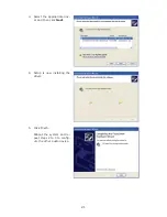
Page 21: ...21 3 Select the appropriate driv er and then click Next 4 Setup is now installing the driver 5 Click Finish Reboot the system and re peat steps 2 to 5 to config ure the other audio device...

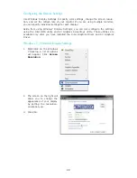
Page 22: ...y Settings you can also configure the settings using the Intel GMA utility and S3 Graphics ScreenToys utility These utilities are available only after you have installed the Intel Graphics Driver and...

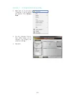
Page 23: ...the Windows 7 desktop A list of options will appear Click Screen Toys Windows 7 S3 Graphics ScreenToys Utility 2 The S3 Graphics Screen Toys utility allows you to manage your display de vices and set...

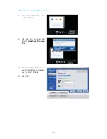
Page 24: ...he notification area of the taskbar Windows 7 Intel GMA Utility 2 Click the blue icon and then select Graphics Proper ties 3 The Intel GMA utility allows you to manage your display devices and setting...

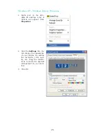
Page 25: ...l appear Click Properties Windows XP Windows Display Properties 2 Click the Settings tab You can change the appearance of your display by setting the resolution color qual ity etc Drag the monitor ico...

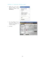
Page 26: ...the Win dows XP desktop A list of options will appear Click ScreenToys Windows XP S3 Graphics ScreenToys Utility 2 The S3 Graphics Screen Toys utility allows you to manage your display de vices and se...

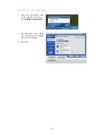
Page 27: ...1 Click the notification area of the taskbar and then se lect Graphics Properties Windows XP Intel GMA Utility 2 The Intel GMA utility allows you to manage your display devices and settings 3 Click O...

Page 28: ...c in Line in Line out 1 Power on select J P6 PCIE x1 1 SATA 2 DC in 12V 1 Front audio 1 1 1 Peripheral power 1 1 SATA 1 SATA 0 1 2 9 10 USB 6 7 Battery 1 Realtek ALC262 1 1 SPI 1 1 2 5 6 Panel power s...

Reviews: