


Chapter 2 Hardware Installation
Chapter 5
www.dfi.com
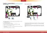
Chapter 5 Ports and Connectors
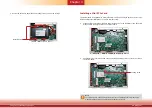
DC-in
1
6
1
1
1
3
1
1
Mini
PCIe
1
12
12
1
Reset Power
Front
Panel
(JP11)
DDR4
DDR4
DDR4
DDR4
COM 4
LAN 2
LAN 1
USB 2
USB 1
USB 3.0
USB 4
USB 3
COM 3
COM 2
COM 1
VGA
USB 3.0
SATA 3.0
SPI Flash
BIOS
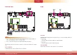
JP2
JP1
Battery
JP7
Mini
PCIe
MIC-in
LINE-out
DP or HDMI
SATA 2 SATA Power
Realtek ALC888
Intel
WGI210AT
JP3
JP4
COM4/DIO Pin Select
COM4/DIO Pin Select
Clear CMOS
Mini PCIe PCIe/
SATA Select
(JP3)
(JP4)
Auto PWR ON
(JP1)
(JP2)
(JP7)
1
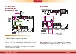
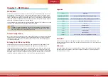
Front Panel Connector
HDD-LED - HDD LED
This LED will be lit when the hard drive is being accessed.
RESET-SW - Reset Switch
This switch allows you to reboot without having to power off the system.
PWR-BTN - Power Switch
This switch is used to power on or off the system.
PWR-LED - Power/Standby LED
When the system’s power is on, this LED will be lit. When the system is in the S1 (POS - Pow-
er On Suspend) state, it will blink every second. When the system is in the S3 (STR - Suspend
To RAM) state, it will blink every 4 seconds.
Pin Pin Assignment
Pin Pin Assignment
HDD-LED
6
HDD Power
PWR Button
1
Power Button
3
Ground
3
Ground
RESET-SW
3
Ground
PWR LED
2
Power LED
5
RST Signal
3
Ground
Suspend
Mode LED
3
Ground
4
SUS LED
HDD_LED
Power_LED
Reset Button
Power Button
1 2
5 6
SUS_LED