DFI EC531-SD Installation Manual Download Page 7

7

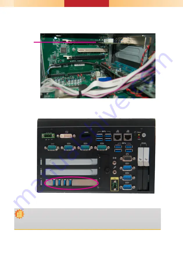
2.  Insert the expansion card into a PCI or PCIe slot on the riser card and secure 

the bracket in place.


Rear View

PCIe card

Note:

The  EC531-SD  has  one  PCIe  x16  slot  and  two  PCI  slots  with  the 

H320-2P1E

  card, 

whereas  the  EC532-SD  has  two  PCIe  x16  slots  and  one  PCI  slot  with  the 

H320-

1P2E card.

Summary of Contents for EC531-SD

Page 1: ...o the product s release For the latest revision and details of the installation process please refer to the user s manual Notes 1 Please gently press the power button to avoid possible damages 2 The H...

Page 2: ...y Note that the HDD should be positioned vertically with the SATA power connector on top of the data connector to correctly engage with the system s SATA connectors Then close the drive bay and lock t...

Page 3: ...re the system and all other peripherals connected to it have been powered off 2 Disconnect all power cords and external cables 2 The 4 mounting screws on the bottom of the system are used to secure th...

Page 4: ...t the memory into the socket at an angle and push it down until you feel a click SODIMM module Notes 1 The system supports dual channel configuration To enable dual channel populate both SODIMM socket...

Page 5: ...PCIe card 1 Grasp the Mini PCIe card by its edges and align the notch in the connector of the Mini PCIe card with the notch in the connector on the system board Mounting screw Note The system also has...

Page 6: ...90mm as shown in the picture below in order to fit expansion slots 1 PCI and PCIe slots on the riser card inside the system are used to install the expansion cards To install the expansion cards you n...

Page 7: ...CIe slot on the riser card and secure the bracket in place Rear View PCIe card Note The EC531 SD has one PCIe x16 slot and two PCI slots with the H320 2P1E card whereas the EC532 SD has two PCIe x16 s...

Page 8: ...CMOS Data JP1 Normal default 1 2 On Clear CMOS Data 2 3 On RS232 422 485 Select COM 1 JP5 JP12 COM 2 JP7 JP14 RS232 default 1 3 2 4 On RS422 Full Duplex RS485 3 5 4 6 On RS232 422 485 Select COM 1 JP6...

Page 9: ...lt 1 3 2 4 On RS422 Full Duplex RS485 3 5 4 6 On RS232 422 485 Select COM 6 JP12 RS232 default 1 2 On RS422 Full Duplex 3 4 On RS485 5 6 On 1 6 JP7 1 6 JP2 1 6 JP3 1 6 JP1 1 6 JP5 1 6 JP6 1 6 JP4 1 6...

Reviews: