

7
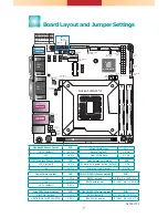
Board Layout and Jumper Settings
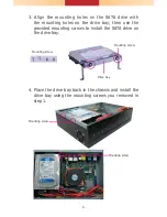
1
SATA 3
LAN 1
USB 1-2
DVI-I
DP++
LAN 2
USB 3-4
COM1
VGA
Mic-in
Line-out
USB 3.0
USB 3.0
PS/2
USB 5-6
USB 2.0
PCIe x16
Buzzer
Intel
H110/Q170
1
SATA 0
1
SATA 2
Mini PCIe
LPC
1
13
2
14
13
1
12
24
ATX power
1
1
2
Battery
+12V
Power
1
2
4
3
Realtek ALC888
Intel
WGI211AT
1
Chassis
Intrusion
Socket LGA1151
DDR4_2 SODIMM
DDR4_1 SODIMM
39
40
2
1
LVDS LCD Panel
9
1
2
10
9
1
2
10
USB 2.0
USB 7-8
USB 11-12
(Only for
SD100-Q170)
10
9
1
2
10
9
1
2
10
9
1
2
COM 2
COM 3 COM 4
1
2
5
6
1
2
5
6
1
2
5
6
1
LCD/Inverter
Power
1
1
Mini PCIe Select
LVDS Inverter Power
COM1 RS232/Power
Select
LVDS Power Select
COM2 RS232/Power
Select
(JP7)
(JP6)
(JP8)
(JP1)
(JP2)
SPI Flash
BIOS
(JP1) (JP2)
(JP7)
(JP8)
(JP6)
Digital
I/O
Digital I/O
Power
1 2
1112
Front
Panel
1
Auto
Power-on
(JP5)
1
System
Fan 1
1
Clear
CMOS
(JP4)
1
LVDS Back Light
Select (JP3)
1
System
Fan 2
S/PDIF
1
1
2
5
6
SMBus
1
CPU Fan
ASMedia
ASM1442
Standby
Power LED
Auto Power-on Select
JP5
Power-on via power button (default) 1-2
On
Power-on via AC power
2-3 On
Mini PCIe Signal Select
JP1
Mini PCIe (default)
1-2 On
mSATA (Only for SD100-Q170)
2-3 On
LCD/Inverter Power Select
JP2
+12V (default)
1-2 On
+5V 2-3
On
Panel Power Select
JP7
+12V
1-2 On
+5V 3-4
On
+3.3V (default)
5-6 On
Backlight Power Select
JP3
+3.3V (default)
1-2 On
+5V 2-3
On
Clear CMOS Data
JP4
Normal (default)
1-2 On
Clear CMOS Data
2-3 On
COM 1 RS232/Power Select
JP6
RS232 (default) 1-3 (RI), 2-4 (DCD) On
RS232 with power
3-5 (+5V), 4-6 (+12V) On
COM 2 RS232/Power Select
JP8
RS232 (default) 1-3 (RI), 2-4 (DCD) On
RS232 with power
3-5 (+5V), 4-6 (+12V) On
A45001702