background image

SIRIUSi-XHS®

TECHNICAL REFERENCE MANUAL

4.3. LV: Specifications

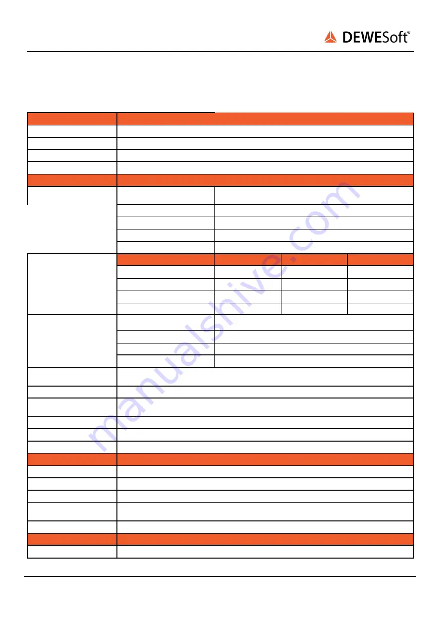
The LV modules are perfect for low voltage and current measurements in combination with current
clamps.

Inputs

Voltage

ADC Type

Hybrid ADC - 24-bit alias free up to 1 MS/s, 16-bit up to 15 MS/s

Sampling Rate

Simultaneous 15 MS/s

Filtering

AAF 1 MHz (6th order)

Analog bandwidth (-3 dB)

5 MHz

Voltage ranges

±100, 50, 20, 10, 5, 2, 1, 0.5, 0.2, 0.1 and 0.05 V

Input Accuracy

DC

±0.03 % of reading ±0.02 % of range ±100 μV (2 mV for Ranges ≥ 10

V)

Up to 1 kHz

±0.03 % of reading ±0.02 % of range

Up to 10 kHz

±0.1 % of reading ±0.05 % of range

Up to 100 kHz

±2 % of reading ±0.1 % of range

Up to 1000 kHz

±5 % of reading ±0.5 % of range

Noise floor, Typ.

Sample rate, filter \ Range →

100 V

5 V

0.5 V

15 MS/s, Filter off

-82 dB

-78 dB

-65 dB

1 MS/s, Filter on

-94 dB

-95 dB

-88 dB

100 kS/s, Filter on

-104 dB

-105 dB

-100 dB

10 kS/s, Filter on

-113 dB

-114 dB

-107 dB

CMR, Typ.

Frequency \ Range →

100 V

5 V

0.5 V

50 Hz

91 dB

102 dB

98 dB

400 Hz

86 dB

75 dB

90 dB

10 kHz

66 dB

74 dB

82 dB

Channel Crosstalk

Range ≥ 10 V: -105 dB @ 10 kHz

Range < 10 V: -120 dB @ 10 kHz

Gain Drift

Typical 10 ppm/K, max. 30 ppm/K

Offset Drift

Range ≥ 10 V: Typ. 100 μV/K + 1 ppm of range/K, Max 250 μV/K + 2 ppm of range/K

Range < 10 V: Typ. 4 μV/K + 1 ppm of range/K, Max 8 μV/K + 2 ppm of range/K

Gain Linearity

< 0.03 %

Input Coupling (see 1)

DC, AC 1 Hz (3 Hz, 10 Hz per SW)

Input Impedance

Range < 10 V: 10 MΩ; Range ≥ 10 V: 1 MΩ || 110 pF between INx to GND

Excitation Voltage

Unipolar or Bipolar Software selectable (programmable 16-bit DAC)

Excitation Level

unipolar 2 .. 24 V; Predefined levels: 2, 2.5, 5, 10, 12, 15, 20 and 24 VDC

Excitation Level

bipolar 2.5 .. 30 V; Predefined levels: 2.5, 5, 10, 12, 15, 24 and 30 VDC

Drift

±10 ppm/K ±150 μV/K

Stability 10% to 90% load

(bipolar)

< 0.01 %

Current limit

200 mA (2 Watt max. per Channel, 12 Watt max. per Slice)

Additional Specifications

Input connector

DSUB 9, BNC (others on request)

SIRIUSi-XHS® - V21-2

37/52

Summary of Contents for SIRIUSi-XHS

Page 1: ...SIRIUSi XHS TECHNICAL REFERENCE MANUAL SIRIUSi XHS V21 2...

Page 2: ...oftX settings for SIRIUSi XHS 10 2 2 4 Channel Setup SIRIUSi XHS 16 2 3 Simple Measurement 17 2 3 1 Help Manual 17 2 3 2 Analogue channel setup 17 2 3 3 Sample rate 18 2 3 4 Measurement Mode 19 2 3 5...

Page 3: ...t settings 43 5 1 2 XCP Event settings 43 5 1 3 XCP outputs channels 44 5 1 4 Generating A2L file 45 5 1 5 Download and Upload button 45 5 2 Start the XCP protocol 45 6 Troubleshooting 46 6 1 Device n...

Page 4: ...nnection variants and the pin assignments on the inputs and outputs A comprehensive introduction to the configuration of the modules using DewesoftX Detailed technical data Specifications etc 1 1 Lege...

Page 5: ...XHS technical reference manual 1 2 2 DewesoftX User Manual The DewesoftX tutorials document provides basics and additional information and examples for working with DewesoftX and certain parts of the...

Page 6: ...Hint As Siriusi XHS is a new device and its software functionality is still in the development phase we recommend using the latest Development or Release Candidate versions As the FW of the device is...

Page 7: ...connector on the back of the XHS device Finally connect the other side of the USB cable with the USB A connector to the PC You can find advanced connections in chapter Image 2 USB connection 2 2 1 1 S...

Page 8: ...5 MS s 8 1 MS s 2 2 2 2 Ethernet configuration on the PC As SIRIUSi XHS is a network device with static IP you need to adjust the Network Card settings when connecting it via Ethernet The ethernet por...

Page 9: ...roubleshooting If DewesoftX doesn t detect your devices you should try pinging them via command prompt In command prompt write ping IP replace IP with IP that is set on your device The result should b...

Page 10: ...right and then on the Settings item in the pop up to open the DewesoftX settings dialogue Image 6 DewesoftX settings In case the XHS device is connected via USB the device will automatically be liste...

Page 11: ...RT device and therefore needs to be configured in that way Adding a new XHS device is done by clicking the plus button in the device screen This will show the Add device window where you can find and...

Page 12: ...From the 2020 2 Release candidate version the RT device option is no longer experimental In older software versions the Support of RT devices is still an Experimental feature and it needs to be enabl...

Page 13: ...will see a new SIRIUSi XHS or Dewesoft RT connection in the device tree Image 9 RT device Connection If the text by the device is disconnected you should click on the device Dewesoft RT Connection se...

Page 14: ...SIRIUSi XHS TECHNICAL REFERENCE MANUAL Image 10 Setting IP If everything is set correctly both devices should be detected as SiriusXHS devices SIRIUSi XHS V21 2 14 52...

Page 15: ...Local system and selecting time source When you have only one device you can select the Dewesoft DAQ devices and Automatic Standalone mode Image 12 Setting synchronization When you have multiple XHS d...

Page 16: ...s Hint When you click on a connector in the image the corresponding channel in the Channel setup grid will automatically be selected This also works the other way around when you select a channel or m...

Page 17: ...our connected SIRIUS systems Per default only the first channel will be set to Used Unused channels will not show up in measure mode and can thus not be used for display calculations or storing thus w...

Page 18: ...in a time domain with a good time resolution you should sample 10 to 20 times faster than the frequency of the signal that you want to measure e g 1 kS s for a 50 Hz sine wave If you have a lot of hig...

Page 19: ...rent widgets which are depending on the selected measurement screen In this case we see a simple recorder widget where data is presented in time domain You can use the channel selector list to assign...

Page 20: ...e selected channel of the data file Now you can use the cursors to analyse your data zoom in and out of the data click Offline math to add computations based on your data etc You can also change the d...

Page 21: ...rmwares folder of your Dewesoft installation e g D DewesoftX System X3 Firmwares Connect the Dewesoft instrument to the PC and run Dewesoft X3 Go to settings under the Update tab If the firmware packa...

Page 22: ...ffline license in case the system doesn t have an internet connection Offline license can be registered on a different PC with the internet connection If needed the license can also be written on the...

Page 23: ...t now Make sure that you have started DewesoftX version Release Candidate 2020 2 Development 2021 1 or higher Make sure that the external power supply is connected and okay Disconnect the network cabl...

Page 24: ...nt recording and very high dynamic alias free acquisition software selectable per channel Modern interfaces and protocols allow open and flexible connectivity Voltage High Voltage Current IEPE Charge...

Page 25: ...AN interface allows the distribution of devices with PTPv2 synchronization the USB3 interface allows the fastest data transfers with a quick connection to the computer OPEN PROTOCOLS data is transferr...

Page 26: ...nel depending on the application the appropriate mode of ADC operation 3 1 2 Perfect synchronization If you mix channels from Sigma Delta and SAR devices high bandwidth and alias free then channels ar...

Page 27: ...ges over other DAQ systems Functionalities like plug and play hardware auto detection smart TEDS sensors advanced storing and data analysis features will take your measurement and analysis needs to a...

Page 28: ...ide The SIRIUSi XHS chassis has following connectors at the rear side Image 44 SIRIUSi XHS Rear side Name Description CAN CAN bus DSUB 9 male connector SYNC Two 4 pin LEMO female sync connectors USB U...

Page 29: ...302 CLA Mating connector for the cable FGJ 1B 302 CLLD52Z 3 5 1 1 Power out connector Power out connector pin out 2 pin LEMO female Pin Name Description 1 V Supply 2 V Ground Power Out connector on th...

Page 30: ...on 1 CLK Clock 2 Trigg Trigger 3 GPS PPS GPS PPS 4 DGND Digital Ground Interface connector EEG 00 304 CLL Mating connector FGG 00 304 CLAD27Z Important When IRIG synchronisation is used the IRIG diffe...

Page 31: ...rrect measurements it is highly recommended to ground the SIRIUS The GND connector is usually a banana connector There may also be a screw connector e g SIRIUS R8 Warning It is mandatory to connect a...

Page 32: ...on 1 Tx A Transmitting pair A 2 Tx A Transmitting pair A 3 Rx B Receiving pair B 4 Tx C Transmitting pair C 5 Tx C Transmitting pair C 6 Rx B Receiving pair B 7 Rx D Receiving pair D 8 Rx C Receiving...

Page 33: ...z Sensor excitation 2 5 30 V bipolar 2 24 V unipolar max 0 2 A 2 W IEPE 2 mA 4 mA 8 mA 12 mA 16 mA 20 mA Bridge connection Full Programmable shunt IEPE input DSI ACC Resistance Temperature PTx DSI RTD...

Page 34: ...SIRIUSi XHS TECHNICAL REFERENCE MANUAL 4 1 SIRIUSi XHS dimensions Image 52 Dimensions SIRIUSi XHS V21 2 34 52...

Page 35: ...o 100 kHz 4 of reading 0 1 of range Up to 1000 kHz 5 of reading 0 5 of range Noise floor Typ Sample rate Range 2000 V 1000 V 400 V 200 V 15 MS s 84 dB 82 dB 79 dB 75 dB 1 MS s 95 dB 93 dB 85 dB 78 dB...

Page 36: ...2 2 HV Banana Connector HV connector pin out Banana plug SIRIUSi XHS 8xHV Warning It is mandatory to connect a ground cable to the GND connector of the SIRIUS when you are working with high voltages...

Page 37: ...s Filter on 113 dB 114 dB 107 dB CMR Typ Frequency Range 100 V 5 V 0 5 V 50 Hz 91 dB 102 dB 98 dB 400 Hz 86 dB 75 dB 90 dB 10 kHz 66 dB 74 dB 82 dB Channel Crosstalk Range 10 V 105 dB 10 kHz Range 10...

Page 38: ...adapters Rev 1617026400 1 In must be within 10V referred to GND iso for Ranges 10 V the DC value of In is not rejected 4 3 1 LV DSUB connector LV connector pin out DSUB 9 female SIRIUSi XHS 8xLV 4 3...

Page 39: ...SIRIUSi XHS TECHNICAL REFERENCE MANUAL 4 3 1 2 LV Current 4 3 2 LV BNC connector LV BNC connector pin out BNC SIRIUSi XHS 8xLV BNC SIRIUSi XHS V21 2 39 52...

Page 40: ...0 4 V 15 MS s Filter off 88 dB 88 dB 88 dB 87 dB 76 dB 1 MS s Filter on 99 dB 99 dB 97 dB 95 dB 92 dB 100 kS s Filter on 109 dB 107 dB 108 dB 107 dB 103 dB 10 kS s Filter on 120 dB 120 dB 119 dB 118...

Page 41: ...ection Shortcut 4 V Open 19 V Additional Specifications Input connector BNC TEDS support IEPE mode only Rev 1615795200 4 4 1 ACC BNC connector ACC connector pin out BNC SIRIUSi XHS 8xACC 4 4 1 1 ACC V...

Page 42: ...the device When the settings are done and the RT mode is properly started Dewesoft can be closed The maximum sample rate for data transmitted over the XCP protocol is 1Mhz 5 1 XCP Slave module settin...

Page 43: ...device Under the port setting you can set on which port the XCP slave will open the connection The default setting is 5555 5 1 2 XCP Event settings The XCP Event settings will be recalculated from the...

Page 44: ...5 1 3 XCP outputs channels This section is for setting up the XCP outputs Here you can just click the Auto Generate button which will populate the list with all available device channels which are se...

Page 45: ...oad button is added that can Read the settings directly from the device once they are properly uploaded 5 2 Start the XCP protocol When all the settings are set the device needs to be put in the RT mo...

Page 46: ...soft the user needs to disable the Opto Stream drivers in the Ethernet network card Opto Stream drivers disabled 6 2 Clear static configuration In any case that the device got stuck in channel setup a...

Page 47: ...these components required the extraction and use of natural resources The substances contained in the system could be harmful to your health and to the environment if the system is improperly handled...

Page 48: ...er cord since it has to be accessible for the users DO NOT use the system if equipment covers or shields are removed If you assume the system is damaged get it examined by authorized personnel only Ad...

Page 49: ...sed specifications Use measurement leads or measurement accessories aligned with the specification of the system only Fire hazard in case of overload Do not switch on the system after transporting it...

Page 50: ...nt needs to be calibrated at regular intervals We recommend annual calibration Before your Dewesoft data acquisition system is delivered it is calibrated Detailed calibration reports for your Dewesoft...

Page 51: ...Trademarks We take pride in our products and we take care that all key products and technologies are registered as trademarks all over the world The Dewesoft name is a registered trademark Product fa...

Page 52: ...RENCE MANUAL 8 9 Documentation version Doc Version Date dd mm yyyy Notes V21 2 4 4 2021 License on the device additional V20 1 18 1 2021 Added XCP opton Few small fixes V20 1 13 05 2020 Initial versio...

Reviews: