background image

9

6.

Insert long end (A) Fig. 16, of quickset blade

changing wrench into hole (G) in lower blade holder. This
will help align wrench (C) with blade holder screw (H).

7.

Turn wrench (E) Fig. 17, counterclockwise to loosen

screw (H) and remove blade (F) from lower blade holder.

8.

Insert new blade into the lower and upper blade

holders in the same manner, making certain the blade
teeth are pointing down toward the table. Tighten screws
in both the upper and lower blade holders. Replace table
insert.

9.

Apply blade tension by referring to the section

“ADJUSTING BLADE TENSION”.

H

G

A

C

Fig. 16

Fig. 17

F

H

E

ADJUSTING
BLADE TENSION

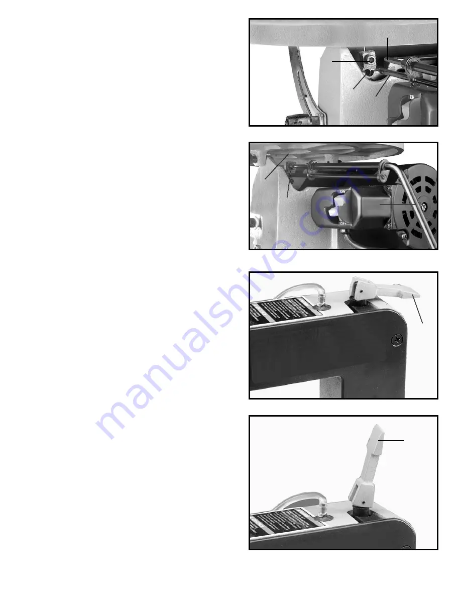
Tension is applied to the blade when the blade tension
lever (A) Fig. 18, has been adjusted and is in the
horizontal position as shown. When the blade tension
lever (A) is moved to the vertical position, as shown in
Fig. 19, blade tension is released.

To adjust blade tension, position lever (A) in the vertical
position, as shown in Fig. 19. To increase tension, turn
lever (A) clockwise and to decrease tension turn lever (A)
counterclockwise. When adjusting tension, turn lever
one-quarter of a turn at a time.

NOTE:

It is necessary to

adjust the blade tension only when the blade is removed
from both the upper and lower blade holders and a new
or different type of blade is assembled to the holders. It
is not necessary to adjust blade tension when the blade
is removed and replaced in only the upper blade holder
as in performing inside cutting operations. After desired
tension is obtained, position tension lever (A) in the
horizontal position, as shown in Fig. 18.

Adjusting the blade for proper tension is usually
accomplished by trial and error. One method is to pull
back on the blade tension lever (A) Fig. 19, the blade
should start to have tension (resistance) when the blade
tension lever is half way between open Fig. 19, and
closed Fig. 18. Finer blades require more tensioning
while thicker blades require less tension.

A

Fig. 18

Fig. 19

A

Summary of Contents for SS200

Page 1: ...NO 905591 05 31 02 Copyright 2002 Delta Machinery ESPAÑOL PÁGINA 15 To learn more about DELTA MACHINERY visit our website at www deltamachinery com For Parts Service Warranty or other Assistance please call 1 800 223 7278 In Canada call 1 800 463 3582 ...

Page 2: ...ry to get caught in moving parts Nonslip footwear is recommended Wear protective hair covering to contain long hair 12 SECURE WORK Use clamps or a vise to hold work when practical It s safer than using your hand and frees both hands to operate tool 13 DON T OVERREACH Keep proper footing and balance at all times 14 MAINTAIN TOOLS IN TOP CONDITION Keep tools sharp and clean for best and safest perfo...

Page 3: ...chments and accessories not recommended by Delta may result in the risk of injuries 20 ALWAYS hold the work firmly against the table 21 DO NOT feed the material too fast while cutting Only feed the material fast enough so that the blade will cut 22 NEVER start the Scroll Saw with the stock pressed against the blade 23 WHEN cutting a large workpiece MAKE SURE the material is supported at table heig...

Page 4: ...apter should be used only until a properly grounded outlet can be installed by a qualified electrician The green colored rigid ear lug and the like extending from the adapter must be connected to a permanent ground such as a properly grounded outlet box Whenever the adapter is used it must be held in place with a metal screw NOTE In Canada the use of a temporary adapter is not permitted by the Can...

Page 5: ...oistened with kerosene do not use acetone gasoline or lacquer thinner for this purpose After cleaning cover the unpainted surfaces with a good quality household floor paste wax NOTICE THE MANUAL COVER PHOTO ILLUSTRATES THE CURRENT PRODUCTION MODEL ALL OTHER ILLUSTRATIONS ARE REPRESENTATIVE ONLY AND MAY NOT DEPICT THE ACTUAL COLOR LABELING OR ACCESSORIES AND MAY BE INTENDED TO ILLUSTRATE TECHNIQUE ...

Page 6: ... Then tighten lock handle K Connect end of air hose M to air nozzle N as shown 3 Position table B Fig 6 on the machine as shown making sure pin O in rear table casting is engaged with hole in base casting Insert pivot bolt E through hole in table casting P and thread into base Q using the 6mm wrench Thread M6 hex nut on end of pivot bolt E Make sure the tilt scale R Fig 7 is positioned inside poin...

Page 7: ...C clamps NOTE For proper stability the holes in the mounting board must be countersunk at the bottom so that the fastener heads are flush with the bottom surface of the mounting board A Fig 10 OPERATING CONTROLS AND ADJUSTMENTS Fig 11 A Fig 12 B ON OFF SWITCH The on off switch A Fig 11 is located on the motor directly under the right hand side of the table To turn the saw ON move the switch A up t...

Page 8: ...WER SOURCE 2 Remove table insert 3 Position blade tension lever A Fig 19 in the vertical position to release blade tension 4 Insert long end A Fig 14 of quickset blade changing wrench into hole B in upper blade holder This will align wrench C with blade holder screw D 5 Fig 15 illustrates the quickset blade changing wrench E engaged with the upper blade holder assembly Turn wrench counterclockwise...

Page 9: ...de tension position lever A in the vertical position as shown in Fig 19 To increase tension turn lever A clockwise and to decrease tension turn lever A counterclockwise When adjusting tension turn lever one quarter of a turn at a time NOTE It is necessary to adjust the blade tension only when the blade is removed from both the upper and lower blade holders and a new or different type of blade is a...

Page 10: ...he holddown C can be adjusted to lay flat on the stock If the workpiece is too thick causing the stock to contact the holddown arm D the complete holddown assembly can be removed since thick stock is heavy enough to resist lifting off the table during the blade s up stroke B Fig 20 Fig 21 D C ADJUSTING THE TABLE 1 Loosen the table locking handle and tilt the table all the way to the right 2 Place ...

Page 11: ... do with your saw Always hold the work firmly against the table and do not feed the workpiece too fast while cutting Feed the workpiece only fast enough so that the blade will cut Scroll saws cut faster across the grain than they do with the grain Allow for this tendency when cutting patterns that shift rather quickly from with the grain cuts to cross grain cuts Make relief cuts before cutting lon...

Page 12: ... blade tension lever to the vertical position 4 Remove the two pivot bolts and wave washers C Fig 27 5 Fig 28 illustrates one of the pivot bolts and wave washers C removed Thoroughly clean grease from shafts of both pivot bolts and lubricate shafts with a few drops of light machine oil 6 Re assemble the two pivot bolts and replace side panel Re apply tension to the blade A A B Fig 26 C Fig 27 C Fi...

Page 13: ... for medium to soft materials 3 Use a blade that will have 2 teeth in the workpiece at all times 4 Most blade packaging is marked with the size of the wood the blade is intended to cut and the minimum radius which can be cut with that blade BLADE BREAKAGE Blade breakage is usually caused by one or more of the following 1 Bending the blade during installation 2 Improper blade tension 3 Improper bla...

Page 14: ...a s sole warranty and sets forth the customer s exclusive remedy with respect to defective products all other warranties express or implied whether of merchantability fitness for purpose or otherwise are expressly disclaimed by Delta Printed in U S A PARTS SERVICE OR WARRANTY ASSISTANCE All Delta Machines and accessories are manufactured to high quality standards and are serviced by a network of P...

Reviews: