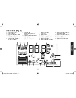
English
21
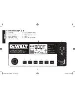
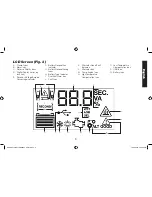
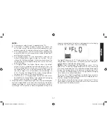
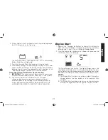
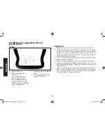
4. If the unit detects that the alternator is out of typical voltage range,
the LCD Screen shows the following:
The Fault Icon will flash. The Alternator Icon, “ALT” and the (empty)
Battery Status Icon will light solid.
5. Press the Alternator Check Button again to stop the check.
6. When disconnecting the battery charger, unplug the AC Power
Cord, and then disconnect the battery charger from the battery
following the last step of the appropriate set of directions in the
“Preparing to Charge” section of this Instruction Manual.
Notes Concerning the Alternator Check Function:
A.
IMPORTANT:
This check may not be accurate for every make,
manufacturer and model of vehicle. Check only 12 volt systems.
B. The unit may detect that the alternator is out of typical
voltage range because someone has added a number of
accessory loads on the charging system, thereby increasing
current demand from the alternator. MAKE SURE THAT THE
ALTERNATOR IS RATED TO SUPPORT THE APPLICATION.
Engine Start
1. Refer to the “Charging the Battery” section of this Instruction
Manual. Set up the battery charger and connect to the battery
following steps 1 and 2. The unit will be in Standby Mode.
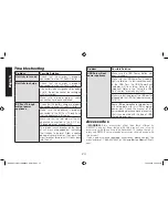
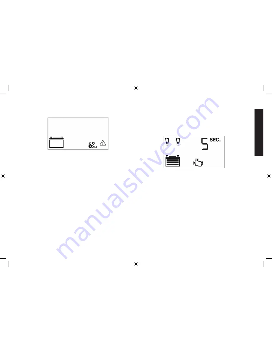
2. Press the Engine Start Button once. A beep will sound and the
LCD Screen shows the following:
The Pump Engine Icon flashes. The Digital Display shows the
countdown to indicate the unit is in Engine Start Mode. The bars
on the Battery Icon will change from empty to solid (bottom to top)
repeatedly. The Clamp Icons and the Battery Icon will light solid.
NOTES:
A. The Engine Start function may not be started if the battery
charger detects that the battery is at full capacity (fully
charged).
B. The Engine Start countdown process can be terminated by
pressing the Engine Start Button again to stop the function.
DXAEC210_ManualENFRSP_092116.indd 21
10/19/2016 3:58:54 PM


