


9
ENglISH
TO REMOVE THE GUARD
1. Loosen the screw holding the cinch collar
around the neck of the spindle.
2. Lift up on the guard.
WARNING:
Never use the tool without
the guard in place.
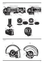
Fitting and Removing a Grinding or
Cutting Disc (fig. 1, 3, 4)
WARNING:
Do not use a
damaged disc.
1. Place the tool on a table, guard up.
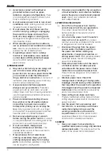
2. Fit the backing flange (d) correctly onto the
spindle (b) (fig. 3).
3. Place the disc (o) on the backing flange (d).
When fitting a disc with a raised centre, make
sure that the raised centre (n) is facing the
backing flange (d).
4. Screw the threaded locking flange (e) onto the
spindle (b) (fig. 4):
a. The ring on the threaded locking flange (e)
must face towards the disc when fitting a
grinding disc (fig. 4A);
b. The ring on the threaded locking flange (e)
must face away from the disc when fitting a
cutting disc (fig. 4B).
5. Press the spindle lock button (a) and rotate the
spindle (b) until it locks in position.
6. Tighten the threaded locking flange (e) with the
hex key provided or a two pin spanner.
7. Release the spindle lock.
8. To remove the disc, loosen the threaded locking
flange (e) with the hex key provided or a two
pin spanner.
NOTE:
Edge grinding can be performed with wheels
designed and specified for this purpose; 6 mm thick
wheels are designed for surface grinding while 3 mm
wheels are designed for edge grinding. Cutting can
be performed by using a cutting wheel and a guard.
Mounting Wire Brushes
and Wire Wheels
Wire cup brushes or wire wheels screw directly
on the grinder spindle without the use of flanges.
Use only wire brushes or wheels provided with a
M14 threaded hub.
CAUTION: Wear work gloves when
handling wire brushes and wheels.
They can become sharp.
WARNING:
Accessories must be rated
for at least the speed recom mended
on the tool warning label. Wheels and
other accessories running over rated
accessory speed may burst and cause
injury. Threaded accessories must
have a M14 hub. Every unthreaded
accessory must have a 22 mm arbor
hole. If it does not, it may have been
designed for a circular saw and should
not be used. Use only the accessories
shown in the chart at the end of this
section. Accessory ratings must be
above listed minimum wheel speed as
shown on tool nameplate.
Mounting Guards
WARNING: To reduce the risk
of serious personal injury, turn
tool off and disconnect tool from
power source before making any
adjustments or removing/installing
attachments or accessories.
Before
reconnecting the tool, depress and
release the trigger switch to ensure that
the tool is off.
CAUTION:
Guards must be used with
this grinder.
When using the DWE8300 or the DWE8310 grinder
for cutting metal or masonry, a guard MUST be
used. Guards are available at extra cost from
D
e
WALT
distributors.
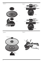
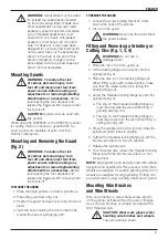
Mounting and Removing the Guard
(fig. 2)
WARNING: To reduce the risk
of serious personal injury, turn
tool off and disconnect tool from
power source before making any
adjustments or removing/installing
attachments or accessories.
Before
reconnecting the tool, depress and
release the trigger switch to ensure that
the tool is off.
TO MOUNT THE GUARD
1. Place the angle grinder on a table, spindle up.
2. Press the guard down (fig. 2A).
3. Postion the guard between your body and work
piece.
4. Tight the screw holding the cinch collar firmly
around the neck of spindle (fig. 2B)