4
replace both brushes. Use of the correct grade of brush is essential
for proper operation of electric brakes on units so equipped. New
brush assemblies are available at your local service center. The tool
should be allowed to “run in” (run at no load without a blade) for 10
minutes before use to seat new brushes. This is especially important
for saws equipped with electric brakes which may be erratic in
operation until the brushes are properly seated (worn in).
While “running in” DO NOT TIE, TAPE, OR OTHERWISE LOCK THE
TRIGGER SWITCH ON. HOLD BY HAND ONLY.
Adjustments and Setup
ATTACHING AND REMOVING BLADES
DISCONNECT PLUG FROM POWER SUPPLY.
To attach the blade, retract lower blade guard and place inner clamp
washer and blade on saw spindle with printed side of blade out (teeth
at bottom of blade pointing forward) (FIG. 1.) Place outer clamp
washer on saw spindle. The larger surfaces of both washers must
face the blade. Thread on blade clamping screw firmly by hand to
hold both blade washers in position.
Lightly depress the blade lock (FIG. 2) while turning the spindle until
the blade stops rotating. Tighten blade clamping screw (clockwise)
firmly with the blade wrench (FIG. 3).
NEVER ENGAGE BLADE LOCK WHILE SAW IS RUNNING, OR
ENGAGE IN AN EFFORT TO STOP THE TOOL. NEVER TURN
SWITCH ON WHEN BLADE LOCK IS ENGAGED. SERIOUS
DAMAGE TO YOUR SAW WILL RESULT.
When removing the blade, first unplug the saw. Engage the blade
lock and unscrew the blade clamping screw by turning it counter-
clockwise with the blade wrench.
CUTTING DEPTH ADJUSTMENT
DISCONNECT PLUG FROM POWER SUPPLY.
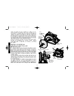
Hold the saw firmly as shown in Figure 4. Loosen (counterclockwise)
the Depth Adjustment Lever and move shoe to obtain the desired
depth of cut, as shown in Figure 5. Make sure the Depth Adjustment
English
FIG. 4
DEPTH
ADJUSTMENT
LEVER
FIG. 5
FIG. 6
GULLET
SURFACE
OF WOOD
FIG. 7
RIP FENCE
TIP OF TOOTH
TIP OF TOOTH
FIG. 5A
FIG. 5B
GULLET
SURFACE
OF WOOD
382782-00/DW359 7/18/00 10:59 AM Page 4


