5
NOTE:
Align ribs on inside of depth locator with grooves in clutch housing.
DEPTH ADJUSTMENT
1. For washer head screws: rotate adjustment collar until end of nutsetter is flush
with end of locator.
2. For large washer head and sealer screws: adjust as above until nutsetter is
recessed approximately 1.6 mm (1/16") into the locator.
3. Test drive a fastener in scrap material to determine if seating is correct.
4. Adjust following the graphic printed on the tool.
VERSA CLUTCH™ UNITS (DW268-XE AND DW269-XE)
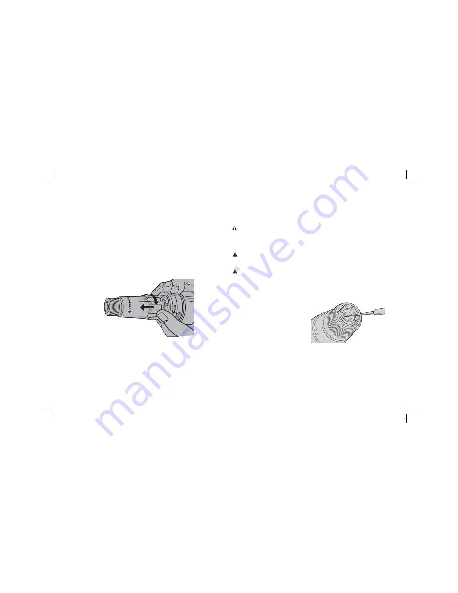
External adjustment of all Versa Clutch™ units for a wide range of fastener sizes is
fast and easy as follows (Fig. 4):
1. Pull forward, then rotate collar in increase direction (stamped on adjustment
collar) to increase the amount of clutch engagement and torque output.
FIG. 4
VERSA CLUTCH™
2. Maximum rotation of the collar in the increase direction results in full clutch
engagement and maximum torque output and fastener capacity. Collar and
adjustable stop will not screw off clutch housing.
3. Test drive a fastener into a scrap piece to check proper fastener seating. It is
normal after a period of use to require a slightly different collar setting due to
wear on the clutch faces.
NOTE:
With Versa Clutch™, the operator has the ability to “override” clutch ratchet if
a fastener hits a wood knot, variable hardness in steel work pieces or incorrect pilot
holes. Increased operator pressure will usually cause the clutches to pick-up and
continue to seat the fastener. Further, a quick twist of the collar will change the clutch
setting to overcome most driving difficulties and will provide for immediate change in
torque output giving the operator the option to drive a wide range of fastener sizes.
MAINTENANCE
WARNING: To reduce the risk of serious personal injury, turn tool off and
disconnect tool from power source before making any adjustments or removing/
installing attachments or accessories.
An accidental start-up can cause injury.
Cleaning
WARNING:
Blow dirt and dust out of all air vents with clean, dry air at least once
a week. To minimize the risk of eye injury, always wear AS/NZS1337 approved eye
protection when performing this.
WARNING:
Never use solvents or other harsh chemicals for cleaning the
non-metallic parts of the tool. These chemicals may weaken the plastic materials
used in these parts. Use a cloth dampened only with water and mild soap. Never let
any liquid get inside the tool; never immerse any part of the tool into a liquid.
DRYWALL SCREWDRIVERS:
Depth locator and adjustment collar should be removed
and drywall dust blown out of the clutch housing area at least once a week.
Changing Clutches
FIG. 5
1. Remove clutch housing by
unscrewing (left hand thread).
2. Clamp tool or clutch housing in a
resilient clamp. USE CARE, the clutch
housing can be easily damaged.
3. Remove round clutch retaining rings
with a very small screwdriver (Fig. 5).
4. Install new clutches and new retaining rings. (DW274 series only) Be careful
to assemble the intermediate clutch large end first toward the unit and then the
spring. The spring should run against the output clutch.
NOTE:
If the output spindle slides toward inside of gear case, remove gear case and
push output spindle forward to expose retaining ring groove. Reassemble dead spindle
spring allowing no more than 6.35 mm (1/4") projecting from end of spindle.
5. Relubricate clutches.
Summary of Contents for DW266-XE
Page 1: ...DW266 XE DW268 XE DW269 XE SCREWDRIVERS INSTRUCTION MANUAL ...
Page 2: ......
Page 9: ...7 ...
Page 10: ......
Page 11: ......


