


29
EnGLIsh
Belt Hook and Magnetic Bit Holder (Fig. A)
(Optional Accessories)
WARNING: To reduce the risk of serious personal
injury, DO NOT
suspend tool overhead or suspend
objects from the belt hook.
ONLY
hang tool’s belt hook
from a work belt.
WARNING: To reduce the risk of serious personal
injury,
ensure the screw holding the belt hook is secure.
IMPORTanT:
When attaching or replacing a belt hook or
magnetic bit holder, use only the screw that is provided. Be sure
to securely tighten the screw.
A belt hook
8
and magnetic bit holder
10
can be be attached
to either side of the tool using only the screw
9
provided,
to accommodate left- or right-handed users. If the hook or
magnetic bit holder is not desired at all, it can be removed from
the tool.
To move belt hook or magnetic bit holder, remove the screw
9
that holds it in place then reassemble on the opposite side. Be
sure to securely tighten the screw.
OPERATION
Instructions for Use
WARNING:
Always observe the safety instructions and
applicable regulations.
WARNING: To reduce the risk of serious personal
injury, turn tool off and disconnect battery pack
before making any adjustments or removing/
installing attachments or accessories.
An accidental
start-up can cause injury.
Proper Hand Position (Fig. D)
WARNING:
To reduce the risk of serious personal injury,
ALWAYS
use proper hand position as shown.
WARNING:
To reduce the risk of serious personal
injury,
ALWAYS
hold securely in anticipation of a
sudden reaction.
Proper hand position requires one hand on the main handle
11
Variable Speed Trigger Switch (Fig. A)
To turn the tool on, squeeze the trigger switch
1
. To turn
the tool off, release the trigger switch. Your tool is equipped
with a brake. The chuck will stop when the trigger switch is
fully released.
The variable speed switch enables you to start the application at
a slow speed. The further you squeeze the trigger, the faster the
tool will operate. For maximum tool life, use variable speed only
for starting holes or fasteners.
nOTE:
Continuous use in variable speed range is not
recommended. It may damage the switch and should
be avoided.
Forward/Reverse Control Button (Fig. A)
A forward/reverse control button
2
determines the direction of
the tool and also serves as a lock-off button.
To select forward rotation, release the trigger switch and
depress the forward/reverse control button on the right side of
the tool.
To select reverse, depress the forward/reverse control button on
the left side of the tool. The centre position of the control button
locks the tool in the off position. When changing the position of
the control button, be sure the trigger is released.
nOTE:
The first time the tool is run after changing the direction
of rotation, you may hear a click on start up. This is normal and
does not indicate a problem.
Worklights (Fig. A)
There is a worklight
7
located above the trigger switch
1
. The
worklight will be activated when the trigger switch is depressed.
When the trigger is released, the worklight will stay illuminated
for up to 20 seconds. If the trigger switch remains depressed,
the worklights will remain on.
nOTE:
The worklight is for lighting the immediate work surface
and are not intended to be used as a flashlight.
Quick-Release Chuck (Fig. A, C)
WARNING:
Use only impact accessories. Non-impact
accessories may break and cause a hazardous condition.
Inspect accessory prior to use to ensure that it con tains
no cracks.
nOTE:
The chuck accepts 6.35 mm hex accessories and
25.4 mm bit tips only. Using 25.4 mm bits allows better access
in tight spaces.
Place the forward/reverse button
2
in the locked off (centre)
position or remove battery pack before changing accessories.
To install an accessory,
push accessory to fully insert into
chuck
4
. The chuck collar
3
does not need to be pulled up to
lock accessory in place.
To remove an accessory,
pull the chuck collar away from the
front of the tool. Remove the accessory and release the collar.
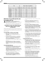
Usage
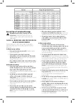
Your impact tool generates the following maximum torque:
Cat #
Nm
Ft.-Lbs.
In.-Lbs
DCF787
170
125
1500
CAUTION:
Ensure fastener and/or system will withstand
the level of torque generated by the tool. Excessive torque
may cause breakage and possible personal injury.
1. Place the accessory on the fastener head. Keep the tool
pointed straight at the fastener.
2. Press switch to start operation. Release the switch to stop
operation. Always check torque with a torque wrench, as
the fastening torque is affected by many factors including
the following:
•
Voltage:
Low voltage, due to a nearly discharged
battery, will reduce fastening torque.
•
Accessory size:
Failure to use the correct accessory
size will cause a reduction in fastening torque.
Summary of Contents for DCF787
Page 1: ...DCF787 Final page size A5 148mm x 210mm ...
Page 3: ...1 Fig A Fig B 8 9 9 10 1 3 4 7 5 6 5 6 2 12 ...
Page 4: ...2 Fig D Fig C 3 11 4 4 3 ...
Page 130: ...128 ...
Page 131: ...129 ...